See what "μH" is in other dictionaries. Self-capacitance of inductors
microhenry
- µH
Dictionary: S. Fadeev. Dictionary of abbreviations of the modern Russian language. - St. Petersburg: Politekhnika, 1997. - 527 p.
. Academician 2015.
See what “μH” is in other dictionaries:
Printed circuit- a unit of electrical or radio equipment made on one board (See Board) in the form of a system of printed electrical and radio elements connected to each other using a printed circuit (See Printed Circuit). In printed version they are made... ...
Slow fluctuation of hemodynamics med. µg micrograms Dictionary: S. Fadeev. Dictionary of abbreviations of the modern Russian language. St. Petersburg: Politekhnika, 1997. 527 p. MKG crawler installation crane Dictionary: S. Fadeev. Dictionary of abbreviations of modern Russian... ... Dictionary of abbreviations and abbreviations
Inductance meters- instruments for measuring the inductance of circuits with lumped parameters, windings of transformers and chokes, inductors, etc. Their operating principles depend on the measurement methods. The “voltmeter-ampermeter” method (Fig. 1)… … Great Soviet Encyclopedia
Inductance coil- an insulated conductor rolled into a spiral, which has significant inductance with a relatively small capacitance and low active resistance. I.K. consists of a single-core, less often multi-core, insulated wire wound on... ... Great Soviet Encyclopedia
SQUID- [from English Superconducting Quantum Interference Device; superconducting quantum interference device; superconducting quantum interferometer (magnetometer)] highly sensitive. Magnetic conversion device flow in electric post signal... Physical encyclopedia
Henry (unit)- This term has other meanings, see Henry. Henry (Russian designation: Gn; international: H) unit of measurement of inductance in the International System of Units (SI). A circuit has an inductance of one henry if the current changes at a rate... ... Wikipedia
Inductor- This term has other meanings, see Coil (meanings). Inductor (choke) on the computer motherboard ... Wikipedia
Inductance coil
Induction coil- Inductor on the computer motherboard. Designation on electrical circuit diagrams. An inductor is a helical, helical or helical coil made of a coiled insulated conductor, with significant ... ... Wikipedia
Law of the power of three second- Graphic representation of the law of the power of three second Law of the power of three second (Child’s law ... Wikipedia
Length and distance converter Mass converter Converter of volume measures of bulk products and food products Area converter Converter of volume and units of measurement in culinary recipes Temperature converter Converter of pressure, mechanical stress, Young's modulus Converter of energy and work Converter of power Converter of force Converter of time Linear speed converter Flat angle Converter thermal efficiency and fuel efficiency Converter of numbers in various number systems Converter of units of measurement of quantity of information Currency rates Women's clothing and shoe sizes Men's clothing and shoe sizes Angular velocity and rotation frequency converter Acceleration converter Angular acceleration converter Density converter Specific volume converter Moment of inertia converter Moment of force converter Torque converter Specific heat of combustion converter (by mass) Energy density and specific heat of combustion converter (by volume) Temperature difference converter Coefficient of thermal expansion converter Thermal resistance converter Thermal conductivity converter Specific heat capacity converter Energy exposure and thermal radiation power converter Heat flux density converter Heat transfer coefficient converter Volume flow rate converter Mass flow rate converter Molar flow rate converter Mass flow density converter Molar concentration converter Mass concentration in solution converter Dynamic (absolute) viscosity converter Kinematic viscosity converter Surface tension converter Vapor permeability converter Water vapor flow density converter Sound level converter Microphone sensitivity converter Converter Sound Pressure Level (SPL) Sound Pressure Level Converter with Selectable Reference Pressure Luminance Converter Luminous Intensity Converter Illuminance Converter Computer Graphics Resolution Converter Frequency and Wavelength Converter Diopter Power and Focal Length Diopter Power and Lens Magnification (×) Converter electric charge Linear charge density converter Surface charge density converter Volume charge density converter Electric current converter Linear current density converter Surface current density converter Electric field strength converter Electrostatic potential and voltage converter Electrical resistance converter Electrical resistivity converter Electrical conductivity converter Electrical conductivity converter Electrical capacitance Inductance Converter American Wire Gauge Converter Levels in dBm (dBm or dBm), dBV (dBV), watts, etc. units Magnetomotive force converter Magnetic field strength converter Magnetic flux converter Magnetic induction converter Radiation. Ionizing radiation absorbed dose rate converter Radioactivity. Radioactive decay converter Radiation. Exposure dose converter Radiation. Absorbed dose converter Decimal prefix converter Data transfer Typography and image processing unit converter Timber volume unit converter Calculation of molar mass Periodic table of chemical elements by D. I. Mendeleev
1 microhenry [µH] = 1E-06 henry [H]
Initial value
Converted value
henry exahenry petahenry terahenry gigahenry megahenry kilohenry hecthenry dekahenry decihenry centihenry millihenry microhenry nanohenry pichenry femtogenry attogenry weber/amp abhenry unit of inductance SGSM stathenry unit of inductance SGSE
Specific heat
More about inductance
Introduction
If someone came up with the idea of conducting a survey of the world's population on the topic “What do you know about inductance?”, the overwhelming number of respondents would simply shrug their shoulders. But this is the second most numerous technical element, after transistors, on which modern civilization is based! Fans of detective stories, remembering that in their youth they read Sir Arthur Conan Doyle’s exciting stories about the adventures of the famous detective Sherlock Holmes, will, with varying degrees of confidence, mutter something about the method that the above-mentioned detective used. At the same time, implying the method of deduction, which, along with the method of induction, is the main method of knowledge in Western philosophy of the New Age.
With the induction method, individual facts, principles are studied and general theoretical concepts are formed based on the results obtained (from particular to general). The deduction method, on the contrary, involves research from general principles and laws, when the provisions of the theory are distributed into individual phenomena.
It should be noted that induction, in the sense of method, does not have any direct relation to inductance, they simply have a common Latin root inductio- guidance, motivation - and mean completely different concepts.
Only a small part of those surveyed from among the exact sciences - professional physicists, electrical engineers, radio engineers and students in these areas - will be able to give a clear answer to this question, and some of them are ready to give an entire lecture on this topic right away.
Definition of inductance
In physics, inductance, or the coefficient of self-induction, is defined as the coefficient of proportionality L between the magnetic flux Ф around a current-carrying conductor and the current I generating it, or - in a more strict formulation - this is the coefficient of proportionality between the electric current flowing in any closed circuit and the magnetic flux created by this current:
Ф = L·I
L = Ф/I
To understand the physical role of the inductor in electrical circuits, one can use the analogy of the formula for the energy stored in it when current I flows with the formula for the mechanical kinetic energy of the body.
For a given current I, inductance L determines the energy of the magnetic field W created by this current I:
W I= 1 / 2 · L · I 2
Similarly, the mechanical kinetic energy of a body is determined by the mass of the body m and its speed V:
Wk= 1 / 2 · m · V 2
That is, inductance, like mass, does not allow the energy of the magnetic field to instantly increase, just as mass does not allow this to happen with the kinetic energy of the body.
Let's study the behavior of current in inductance:


Due to the inertia of the inductance, the fronts of the input voltage are delayed. In automation and radio engineering, such a circuit is called an integrating circuit, and is used to perform the mathematical operation of integration.
Let's study the voltage on the inductor:


At the moments of applying and removing voltage, due to the self-inductive emf inherent in the inductance coils, voltage surges occur. Such a circuit in automation and radio engineering is called differentiating, and is used in automation to correct processes in a controlled object that are fast in nature.
Units
In the SI system of units, inductance is measured in henry, abbreviated as Hn. A circuit carrying current has an inductance of one henry if, when the current changes by one ampere per second, a voltage of one volt appears at the terminals of the circuit.
In variants of the SGS system - the SGSM system and in the Gaussian system, inductance is measured in centimeters (1 H = 10⁹ cm; 1 cm = 1 nH); For centimeters, the name abhenry is also used as a unit of inductance. In the SGSE system, the unit of measurement of inductance is either left nameless or sometimes called stathenry (1 stathenry ≈ 8.987552 10⁻¹¹ henry, the conversion factor is numerically equal to 10⁻⁹ the square of the speed of light, expressed in cm/s).
Historical reference
The symbol L used to denote inductance was adopted in honor of Heinrich Friedrich Emil Lenz, who is known for his contributions to the study of electromagnetism, and who derived Lenz's rule on the properties of induced current. The unit of inductance is named after Joseph Henry, who discovered self-inductance. The term inductance itself was coined by Oliver Heaviside in February 1886.
Among the scientists who took part in the study of the properties of inductance and the development of its various applications, it is necessary to mention Sir Henry Cavendish, who conducted experiments with electricity; Michael Faraday, who discovered electromagnetic induction; Nikola Tesla, who is famous for his work on electrical transmission systems; André-Marie Ampere, who is considered the discoverer of the theory of electromagnetism; Gustav Robert Kirchhoff, who studied electrical circuits; James Clark Maxwell, who studied electromagnetic fields and their particular examples: electricity, magnetism and optics; Henry Rudolf Hertz, who proved that electromagnetic waves do exist; Albert Abraham Michelson and Robert Andrews Millikan. Of course, all these scientists studied other problems that are not mentioned here.
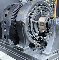
Inductor
By definition, an inductor is a helical, helical or helical coil made of a coiled insulated conductor that has significant inductance with a relatively small capacitance and low active resistance. As a result, when an alternating electric current flows through the coil, its significant inertia is observed, which can be observed in the experiment described above. In high-frequency technology, an inductor can consist of one turn or part of it; in the extreme case, at ultra-high frequencies, a piece of conductor is used to create inductance, which has the so-called distributed inductance (strip lines).
Application in technology
Inductors are used:

- For noise suppression, ripple smoothing, energy storage, alternating current limitation, in resonant (oscillating circuit) and frequency-selective circuits; creating magnetic fields, motion sensors, in credit card readers, as well as in contactless credit cards themselves.
- Inductors (together with capacitors and resistors) are used to construct various circuits with frequency-dependent properties, in particular filters, feedback circuits, oscillating circuits and others. Such coils, accordingly, are called: contour coil, filter coil, and so on.
- Two inductively coupled coils form a transformer.
- An inductor, powered by a pulsed current from a transistor switch, is sometimes used as a high-voltage source of low power in low-current circuits when creating a separate high supply voltage in the power supply is impossible or economically impractical. In this case, high voltage surges appear on the coil due to self-induction, which can be used in the circuit.
- When used to suppress interference, smooth out electrical current ripples, isolate (high-frequency) different parts of the circuit, and store energy in the magnetic field of the core, an inductor is called an inductor.
- In power electrical engineering (to limit the current during, for example, a short circuit of a power line), an inductor is called a reactor.
- Current limiters for welding machines are made in the form of an inductance coil, limiting the current of the welding arc and making it more stable, thereby allowing for a more even and durable weld.
- Inductors are also used as electromagnets - actuators. A cylindrical inductor whose length is much greater than its diameter is called a solenoid. In addition, a solenoid is often called a device that performs mechanical work due to a magnetic field when a ferromagnetic core is retracted.
- In electromagnetic relays, the inductors are called relay windings.
- A heating inductor is a special inductor coil, the working element of induction heating installations and kitchen induction ovens.
By and large, in all electric current generators of any type, as well as in electric motors, their windings are inductor coils. Following the ancient tradition of depicting a flat Earth standing on three elephants or whales, today we could with greater justification assert that life on Earth rests on an inductive coil.
After all, even the Earth’s magnetic field, which protects all terrestrial organisms from corpuscular cosmic and solar radiation, according to the main hypothesis about its origin, is associated with the flow of huge currents in the liquid metal core of the Earth. In essence, this core is a planetary-scale inductor. It is estimated that the zone in which the “magnetic dynamo” mechanism operates is located at a distance of 0.25-0.3 Earth radii.
Rice. 7. Magnetic field around a current-carrying conductor. I- current, B- vector of magnetic induction.
Experiments
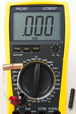
In conclusion, I would like to talk about some interesting properties of inductors that you could observe for yourself if you have the simplest materials and available equipment at hand. To carry out the experiments, we will need pieces of insulated copper wire, a ferrite rod and any modern multimeter with an inductance measurement function. Let us remember that any current-carrying conductor creates around itself a magnetic field of this type, shown in Figure 7.

We wind four dozen turns of wire around the ferrite rod with a small pitch (the distance between the turns). This will be coil #1. Then we wind the same number of turns with the same pitch, but with the opposite direction of winding. This will be coil number 2. And then we wind 20 turns in an arbitrary direction close together. This will be coil number 3. Then carefully remove them from the ferrite rod. The magnetic field of such inductors looks approximately as shown in Fig. 8.
Inductors are divided mainly into two classes: with a magnetic and non-magnetic core. Figure 8 shows a coil with a non-magnetic core, the role of the non-magnetic core is played by air. In Fig. 9 shows examples of inductors with a magnetic core, which can be closed or open.

Ferrite cores and electrical steel plates are mainly used. The cores increase the inductance of the coils significantly. Unlike cylinder-shaped cores, ring-shaped (toroidal) cores allow for higher inductance, since the magnetic flux in them is closed.

Let's connect the ends of the multimeter, turned on in inductance measurement mode, to the ends of coil No. 1. The inductance of such a coil is extremely small, on the order of several fractions of a microhenry, so the device does not show anything (Fig. 10). Let's begin introducing a ferrite rod into the coil (Fig. 11). The device shows about a dozen microhenries, and when the coil moves towards the center of the rod, its inductance increases approximately three times (Fig. 12).

As the coil moves to the other edge of the rod, the inductance value of the coil drops again. Conclusion: the inductance of coils can be adjusted by moving the core in them, and its maximum value is achieved when the coil is located on the ferrite rod (or, conversely, the rod in the coil) in the center. So we got a real, albeit somewhat clumsy, variometer. Having carried out the above experiment with coil No. 2, we will obtain similar results, that is, the direction of winding does not affect the inductance.

Let's place the turns of coil No. 1 or No. 2 on the ferrite rod more tightly, without gaps between the turns, and measure the inductance again. It has increased (Fig. 13).

And when the coil is stretched along the rod, its inductance decreases (Fig. 14). Conclusion: by changing the distance between the turns, you can adjust the inductance, and for maximum inductance, you need to wind the coil “turn to turn”. The technique of adjusting the inductance by stretching or compressing the turns is often used by radio engineers, tuning their transceiver equipment to the desired frequency.
Let's install coil No. 3 on the ferrite rod and measure its inductance (Fig. 15). The number of turns was halved, and the inductance was reduced fourfold. Conclusion: the lower the number of turns, the lower the inductance, and there is no linear relationship between inductance and the number of turns.
Do you find it difficult to translate units of measurement from one language to another? Colleagues are ready to help you. Post a question in TCTerms and within a few minutes you will receive an answer.
The proposed reference information on the marking of chokes and inductors will be especially useful to radio amateurs and electronics engineers when repairing radios and audio equipment. And they are not uncommon in other electronic devices.
They are usually copied by the nominal inductance value and tolerance, i.e. some small deviation from the specified nominal value in percentage. The nominal value is indicated by numbers, and the tolerance by letters. You can see typical examples of marking inductances with alphanumeric codes in the image below.

The most widespread are two types of coding:
The first two digits indicate the value in microhenry (µH), the last two digits indicate the number of zeros. The letter following them indicates tolerance from the face value. For example, inductance marking 272J talks about the denomination 2700 µH, with permission ±5%. If the last letter is not specified, the default tolerance is ±20%. For inductance coils less than 10 µH, the decimal point function is performed by the Latin letter R, and for inductances less than 1 µH - the symbol N. For examples, see the figure below.

The second encoding method is direct marking. In this case, the 680K marking will indicate not 68 µH ±10%, as in the method just above, but 680 µH ±10%.

An excellent collection of utilities used in amateur radio calculations of inductors and various types of oscillatory circuits. Using these programs, you can calculate the coil even for a metal detector without unnecessary problems.
In accordance with the international standard IEC 82, the chokes are coded with color-coded inductance ratings and tolerances. Typically four or three colored dots or rings are used. The first two marks mark the value of the nominal inductance in microhenry (µH), the third is the multiplier, the fourth indicates the tolerance. In the case of three point encoding, a tolerance of 20% is assumed. The colored ring marking the first digit of the denomination may be slightly wider than the others.

Murata inductance marking system |
EC24 series inductance marking system |

The denomination and its permissible deviations are coded using colored stripes. The 1st and 2nd stripes mean two digits of the denomination in microhenry, between which there is a decimal point, the third stripe is the decimal multiplier, the fourth is the precision. For example, the inductor has brown, black, black and silver stripes; its rating is 10×1 = 10 µH with an error of 10%.
See the table below for the purpose of the color stripes:
| Color | 1st and 2nd digits of denomination | Factor | Accuracy |
| Black | 0 | 1 | ±20% |
| Brown | 1 | 10 | - |
| Red | 2 | 100 | - |
| Orange | 3 | 1000 | - |
| Yellow | 4 | - | - |
| Green | 5 | - | - |
| Blue | 6 | - | - |
| Violet | 7 | - | - |
| Grey | 8 | - | - |
| White | 9 | - | - |
| Gold | - | o,1 | ±5% |
| Silver | - | 0,01 | ±10% |
SMD chokes are available in many types of housings, but the housings follow a generally accepted size standard. This greatly simplifies the automatic installation of electronic components. Yes, and for radio amateurs, it is somewhat easier to navigate.

The easiest way to select the right throttle is by looking at catalogs and standard sizes. Standard sizes, as in the case, are indicated using a four-digit code (for example 0805). In this case, “08” indicates the length, and “05” the width in inches. The actual size of such an SMD inductor is 0.08x0.05 inches.
Excellent amateur radio selection by an unknown author on various types of almost all radio components
Length and distance converter Mass converter Converter of volume measures of bulk products and food products Area converter Converter of volume and units of measurement in culinary recipes Temperature converter Converter of pressure, mechanical stress, Young's modulus Converter of energy and work Converter of power Converter of force Converter of time Linear speed converter Flat angle Converter thermal efficiency and fuel efficiency Converter of numbers in various number systems Converter of units of measurement of quantity of information Currency rates Women's clothing and shoe sizes Men's clothing and shoe sizes Angular velocity and rotation frequency converter Acceleration converter Angular acceleration converter Density converter Specific volume converter Moment of inertia converter Moment of force converter Torque converter Specific heat of combustion converter (by mass) Energy density and specific heat of combustion converter (by volume) Temperature difference converter Coefficient of thermal expansion converter Thermal resistance converter Thermal conductivity converter Specific heat capacity converter Energy exposure and thermal radiation power converter Heat flux density converter Heat transfer coefficient converter Volume flow rate converter Mass flow rate converter Molar flow rate converter Mass flow density converter Molar concentration converter Mass concentration in solution converter Dynamic (absolute) viscosity converter Kinematic viscosity converter Surface tension converter Vapor permeability converter Water vapor flow density converter Sound level converter Microphone sensitivity converter Converter Sound Pressure Level (SPL) Sound Pressure Level Converter with Selectable Reference Pressure Luminance Converter Luminous Intensity Converter Illuminance Converter Computer Graphics Resolution Converter Frequency and Wavelength Converter Diopter Power and Focal Length Diopter Power and Lens Magnification (×) Converter electric charge Linear charge density converter Surface charge density converter Volume charge density converter Electric current converter Linear current density converter Surface current density converter Electric field strength converter Electrostatic potential and voltage converter Electrical resistance converter Electrical resistivity converter Electrical conductivity converter Electrical conductivity converter Electrical capacitance Inductance Converter American Wire Gauge Converter Levels in dBm (dBm or dBm), dBV (dBV), watts, etc. units Magnetomotive force converter Magnetic field strength converter Magnetic flux converter Magnetic induction converter Radiation. Ionizing radiation absorbed dose rate converter Radioactivity. Radioactive decay converter Radiation. Exposure dose converter Radiation. Absorbed dose converter Decimal prefix converter Data transfer Typography and image processing unit converter Timber volume unit converter Calculation of molar mass Periodic table of chemical elements by D. I. Mendeleev
1 microhenry [µH] = 0.001 millihenry [mH]
Initial value
Converted value
henry exahenry petahenry terahenry gigahenry megahenry kilohenry hecthenry dekahenry decihenry centihenry millihenry microhenry nanohenry pichenry femtogenry attogenry weber/amp abhenry unit of inductance SGSM stathenry unit of inductance SGSE
Mass concentration in solution
More about inductance
Introduction
If someone came up with the idea of conducting a survey of the world's population on the topic “What do you know about inductance?”, the overwhelming number of respondents would simply shrug their shoulders. But this is the second most numerous technical element, after transistors, on which modern civilization is based! Fans of detective stories, remembering that in their youth they read Sir Arthur Conan Doyle’s exciting stories about the adventures of the famous detective Sherlock Holmes, will, with varying degrees of confidence, mutter something about the method that the above-mentioned detective used. At the same time, implying the method of deduction, which, along with the method of induction, is the main method of knowledge in Western philosophy of the New Age.
With the induction method, individual facts, principles are studied and general theoretical concepts are formed based on the results obtained (from particular to general). The deduction method, on the contrary, involves research from general principles and laws, when the provisions of the theory are distributed into individual phenomena.
It should be noted that induction, in the sense of method, does not have any direct relation to inductance, they simply have a common Latin root inductio- guidance, motivation - and mean completely different concepts.
Only a small part of those surveyed from among the exact sciences - professional physicists, electrical engineers, radio engineers and students in these areas - will be able to give a clear answer to this question, and some of them are ready to give an entire lecture on this topic right away.
Definition of inductance
In physics, inductance, or the coefficient of self-induction, is defined as the coefficient of proportionality L between the magnetic flux Ф around a current-carrying conductor and the current I generating it, or - in a more strict formulation - this is the coefficient of proportionality between the electric current flowing in any closed circuit and the magnetic flux created by this current:
Ф = L·I
L = Ф/I
To understand the physical role of the inductor in electrical circuits, one can use the analogy of the formula for the energy stored in it when current I flows with the formula for the mechanical kinetic energy of the body.
For a given current I, inductance L determines the energy of the magnetic field W created by this current I:
W I= 1 / 2 · L · I 2
Similarly, the mechanical kinetic energy of a body is determined by the mass of the body m and its speed V:
Wk= 1 / 2 · m · V 2
That is, inductance, like mass, does not allow the energy of the magnetic field to instantly increase, just as mass does not allow this to happen with the kinetic energy of the body.
Let's study the behavior of current in inductance:
Due to the inertia of the inductance, the fronts of the input voltage are delayed. In automation and radio engineering, such a circuit is called an integrating circuit, and is used to perform the mathematical operation of integration.
Let's study the voltage on the inductor:
At the moments of applying and removing voltage, due to the self-inductive emf inherent in the inductance coils, voltage surges occur. Such a circuit in automation and radio engineering is called differentiating, and is used in automation to correct processes in a controlled object that are fast in nature.
Units
In the SI system of units, inductance is measured in henry, abbreviated as Hn. A circuit carrying current has an inductance of one henry if, when the current changes by one ampere per second, a voltage of one volt appears at the terminals of the circuit.
In variants of the SGS system - the SGSM system and in the Gaussian system, inductance is measured in centimeters (1 H = 10⁹ cm; 1 cm = 1 nH); For centimeters, the name abhenry is also used as a unit of inductance. In the SGSE system, the unit of measurement of inductance is either left nameless or sometimes called stathenry (1 stathenry ≈ 8.987552 10⁻¹¹ henry, the conversion factor is numerically equal to 10⁻⁹ the square of the speed of light, expressed in cm/s).
Historical reference
The symbol L used to denote inductance was adopted in honor of Heinrich Friedrich Emil Lenz, who is known for his contributions to the study of electromagnetism, and who derived Lenz's rule on the properties of induced current. The unit of inductance is named after Joseph Henry, who discovered self-inductance. The term inductance itself was coined by Oliver Heaviside in February 1886.
Among the scientists who took part in the study of the properties of inductance and the development of its various applications, it is necessary to mention Sir Henry Cavendish, who conducted experiments with electricity; Michael Faraday, who discovered electromagnetic induction; Nikola Tesla, who is famous for his work on electrical transmission systems; André-Marie Ampere, who is considered the discoverer of the theory of electromagnetism; Gustav Robert Kirchhoff, who studied electrical circuits; James Clark Maxwell, who studied electromagnetic fields and their particular examples: electricity, magnetism and optics; Henry Rudolf Hertz, who proved that electromagnetic waves do exist; Albert Abraham Michelson and Robert Andrews Millikan. Of course, all these scientists studied other problems that are not mentioned here.
Inductor
By definition, an inductor is a helical, helical or helical coil made of a coiled insulated conductor that has significant inductance with a relatively small capacitance and low active resistance. As a result, when an alternating electric current flows through the coil, its significant inertia is observed, which can be observed in the experiment described above. In high-frequency technology, an inductor can consist of one turn or part of it; in the extreme case, at ultra-high frequencies, a piece of conductor is used to create inductance, which has the so-called distributed inductance (strip lines).
Application in technology
Inductors are used:
- For noise suppression, ripple smoothing, energy storage, alternating current limitation, in resonant (oscillating circuit) and frequency-selective circuits; creating magnetic fields, motion sensors, in credit card readers, as well as in contactless credit cards themselves.
- Inductors (together with capacitors and resistors) are used to construct various circuits with frequency-dependent properties, in particular filters, feedback circuits, oscillating circuits and others. Such coils, accordingly, are called: contour coil, filter coil, and so on.
- Two inductively coupled coils form a transformer.
- An inductor, powered by a pulsed current from a transistor switch, is sometimes used as a high-voltage source of low power in low-current circuits when creating a separate high supply voltage in the power supply is impossible or economically impractical. In this case, high voltage surges appear on the coil due to self-induction, which can be used in the circuit.
- When used to suppress interference, smooth out electrical current ripples, isolate (high-frequency) different parts of the circuit, and store energy in the magnetic field of the core, an inductor is called an inductor.
- In power electrical engineering (to limit the current during, for example, a short circuit of a power line), an inductor is called a reactor.
- Current limiters for welding machines are made in the form of an inductance coil, limiting the current of the welding arc and making it more stable, thereby allowing for a more even and durable weld.
- Inductors are also used as electromagnets - actuators. A cylindrical inductor whose length is much greater than its diameter is called a solenoid. In addition, a solenoid is often called a device that performs mechanical work due to a magnetic field when a ferromagnetic core is retracted.
- In electromagnetic relays, the inductors are called relay windings.
- A heating inductor is a special inductor coil, the working element of induction heating installations and kitchen induction ovens.
By and large, in all electric current generators of any type, as well as in electric motors, their windings are inductor coils. Following the ancient tradition of depicting a flat Earth standing on three elephants or whales, today we could with greater justification assert that life on Earth rests on an inductive coil.
After all, even the Earth’s magnetic field, which protects all terrestrial organisms from corpuscular cosmic and solar radiation, according to the main hypothesis about its origin, is associated with the flow of huge currents in the liquid metal core of the Earth. In essence, this core is a planetary-scale inductor. It is estimated that the zone in which the “magnetic dynamo” mechanism operates is located at a distance of 0.25-0.3 Earth radii.
Rice. 7. Magnetic field around a current-carrying conductor. I- current, B- vector of magnetic induction.
Experiments
In conclusion, I would like to talk about some interesting properties of inductors that you could observe for yourself if you have the simplest materials and available equipment at hand. To carry out the experiments, we will need pieces of insulated copper wire, a ferrite rod and any modern multimeter with an inductance measurement function. Let us remember that any current-carrying conductor creates around itself a magnetic field of this type, shown in Figure 7.
We wind four dozen turns of wire around the ferrite rod with a small pitch (the distance between the turns). This will be coil #1. Then we wind the same number of turns with the same pitch, but with the opposite direction of winding. This will be coil number 2. And then we wind 20 turns in an arbitrary direction close together. This will be coil number 3. Then carefully remove them from the ferrite rod. The magnetic field of such inductors looks approximately as shown in Fig. 8.
Inductors are divided mainly into two classes: with a magnetic and non-magnetic core. Figure 8 shows a coil with a non-magnetic core, the role of the non-magnetic core is played by air. In Fig. 9 shows examples of inductors with a magnetic core, which can be closed or open.
Ferrite cores and electrical steel plates are mainly used. The cores increase the inductance of the coils significantly. Unlike cylinder-shaped cores, ring-shaped (toroidal) cores allow for higher inductance, since the magnetic flux in them is closed.
Let's connect the ends of the multimeter, turned on in inductance measurement mode, to the ends of coil No. 1. The inductance of such a coil is extremely small, on the order of several fractions of a microhenry, so the device does not show anything (Fig. 10). Let's begin introducing a ferrite rod into the coil (Fig. 11). The device shows about a dozen microhenries, and when the coil moves towards the center of the rod, its inductance increases approximately three times (Fig. 12).
As the coil moves to the other edge of the rod, the inductance value of the coil drops again. Conclusion: the inductance of coils can be adjusted by moving the core in them, and its maximum value is achieved when the coil is located on the ferrite rod (or, conversely, the rod in the coil) in the center. So we got a real, albeit somewhat clumsy, variometer. Having carried out the above experiment with coil No. 2, we will obtain similar results, that is, the direction of winding does not affect the inductance.
Let's place the turns of coil No. 1 or No. 2 on the ferrite rod more tightly, without gaps between the turns, and measure the inductance again. It has increased (Fig. 13).
And when the coil is stretched along the rod, its inductance decreases (Fig. 14). Conclusion: by changing the distance between the turns, you can adjust the inductance, and for maximum inductance, you need to wind the coil “turn to turn”. The technique of adjusting the inductance by stretching or compressing the turns is often used by radio engineers, tuning their transceiver equipment to the desired frequency.
Let's install coil No. 3 on the ferrite rod and measure its inductance (Fig. 15). The number of turns was halved, and the inductance was reduced fourfold. Conclusion: the lower the number of turns, the lower the inductance, and there is no linear relationship between inductance and the number of turns.
Do you find it difficult to translate units of measurement from one language to another? Colleagues are ready to help you. Post a question in TCTerms and within a few minutes you will receive an answer.
- 05.10.2014
This preamplifier is simple and has good parameters. This circuit is based on the TCA5550, containing a dual amplifier and outputs for volume control and equalization, treble, bass, volume, balance. The circuit consumes very little current. Regulators must be located as close to the chip as possible to reduce interference, interference and noise. Element base R1-2-3-4=100 Kohms C3-4=100nF …
- 16.11.2014
The figure shows the circuit of a simple 2-watt amplifier (stereo). The circuit is easy to assemble and has a low cost. Supply voltage 12 V. Load resistance 8 Ohms. Amplifier circuit PCB drawing (stereo)
- 20.09.2014
Its meaning is different for different hard drive models. Unlike high-level formatting - creating partitions and file structures, low-level formatting means basic layout of disk surfaces. For early model hard drives that were supplied with clean surfaces, such formatting creates only information sectors and can be performed by the hard drive controller under the control of the appropriate program. ...
- 20.09.2014
Voltmeters with an error of more than 4% are classified as indicators. One of these voltmeters is described in this article. The voltmeter-indicator whose circuit is shown in the figure can be used to measure voltages in digital devices with a supply voltage of no more than 5V. LED voltmeter indication with a limit from 1.2 to 4.2V through 0.6V. Rin of the voltmeter...
 The story of the pilots who bombed Hiroshima and Nagasaki
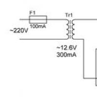 Smooth capacity charging: what to choose?
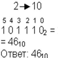 Small Faculty of Mathematics
 “Why do you dream about a round dance in a dream?
 Why do you dream about the church inside: interpretation of the meaning of the dream according to various dream books for men and women
 Dream interpretation of persimmon, why do you dream of persimmon in a dream to see Persimmon in a dream why
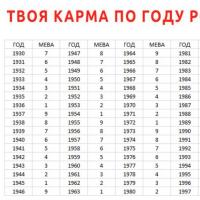 Enchanted soul Meaning of karmic numbers