An attachment for measuring inductance and its use in amateur radio practice. Measuring inductance with improvised means Induction meter
Operating principle device consists of measuring the energy accumulated in a magnetic coil field during the flow of direct current through it.
The proposed device allows you to measure coil inductance at three measurement limits - 30, 300 and 3000 μH with an accuracy of no worse than 2% of the scale value. The readings are not affected by the coil’s own capacitance and its ohmic resistance.
The 2I-NOT elements of the K155LA3 (DDI) microcircuit are used to assemble a rectangular pulse generator, the repetition frequency of which is determined by the capacitance of the capacitor C1, C2 or SZ, depending on the measurement limit switched on by switch SA1. These pulses, through one of the capacitors C4, C5 or C6 and the diode VD2, are supplied to the measured coil Lx, which is connected to terminals XS1 and XS2.
After the cessation of the next pulse during a pause, due to the accumulated energy of the magnetic field, the current through the coil continues to flow in the same direction through the diode VD3, its measurement is carried out by a separate current amplifier assembled on transistors T1, T2 and a pointer device PA1. Capacitor C7 smoothes out current ripples. Diode VD1 serves to bind the level of pulses supplied to the coil.
When setting up the device it is necessary to use three reference coils with inductances of 30, 300 and 3000 μH, which are alternately connected instead of L1, and the corresponding variable resistor R1, R2 or R3 sets the instrument pointer to the maximum scale division. During operation of the meter, it is enough to calibrate with variable resistor R4 at the measurement limit of 300 μH, using coil L1 and turning on switch SB1. The microcircuit is powered from any source with a voltage of 4.5 - 5 V.
The current consumption of each battery is 6 mA. You don’t have to assemble the current amplifier for the milliammeter, but connect a microammeter with a scale of 50 μA and an internal resistance of 2000 Ohms in parallel with capacitor C7. Inductance L1 can be composite, but then the individual coils should be positioned mutually perpendicular or as far apart as possible. For ease of installation, all connecting wires are equipped with plugs, and the corresponding sockets are installed on the boards.
Printed circuit boards

Meter board. View from the conductors

Meter board. View from the parts
Radio Amator 2009 No. 1
Two diagrams of devices for measuring inductance were published in a foreign amateur radio magazine. Considering that since 1991 this magazine has not been supplied to the CIS through the Soyuzpechat system, and the schemes are easy to repeat, it is advisable to briefly familiarize readers of the magazine with them. I am sure that the diagrams are of practical interest to radio amateurs.
Fig.1. Diagram of a device for measuring inductance
In many cases of practical activity of radio amateurs, it is interesting for them, and in some cases necessary, to measure the inductance of inductors or similar radio components that they would like to use in their designs. In the vast majority of cases, simple industrial devices for these purposes are not available, and complex and, accordingly, expensive ones are not available to a wide range of radio amateurs. In both cases, inductance is usually measured using an indirect method. It is converted into a constant voltage “equivalent” to it, as is done in the circuit in Fig. 1, or into a frequency-dependent pulse voltage - Fig. 3. The circuit master oscillator is made on element IC2-A (Fig. 1). As IC2, a CD4584 type microcircuit was used, containing six Schmitt triggers. This microcircuit is found on the radio market, but, alas, it is not very common in our country at present. If difficulties arise with its acquisition, then it is advisable to try to use the domestic 1564TL2 microcircuit or the imported 54NS14. K561TL1 microcircuits (1561TL1, 564TL1) are very common, but they are less “capacious” in terms of the number of Schmitt triggers in one package - there are only four of them. You will have to use two cases of these microcircuits. The inputs and outputs of the IC2-B-IC2-D microcircuits are parallelized. This was done to increase the output of the master oscillator, since it is loaded with low-resistance inductance Lk and resistor R2. The measured inductance is connected to contacts 1-2 of terminal block K3. Through resistor RЗ, the voltage from the inductor Lk is supplied to the input of a pair of inverters IC2-E and IC2-F. The output of the last of these inverters is connected to the integrating circuit R4C2. This chain smoothes out the ripples in the output voltage of IC2-F, so that at pins 1-2 of the output block K2 we obtain almost a direct current voltage. Any high-resistance voltmeter, for example the DT830-B amateur radio tester, is connected to this block (K2). The 9 V voltage supplying the entire device is supplied to block K1. It is then stabilized at 5 V by 78L05 type IC1. In practice, it is possible to use other types of stabilizers that have a slightly higher output voltage, for example 7806 or 7808.
The authors of the article considered it appropriate to slightly increase the potential of the lower plate of capacitor C2 in the circuit relative to the circuit body, bringing it closer to the potential of the upper plate of capacitor C2. For this purpose, potentiometer R2 and voltage divider R5R6 are used.
Now a few words about the parameters of the inductance meter. The device is designed to measure inductance in the range from 200 µH to 5 mH. In the case when a radio amateur needs to measure inductance that is slightly different from the specified range, such an opportunity, of course, exists. It is enough to have in your supply several inductors with pre-measured parameters. For example, having an inductance of 200 μH, you can connect test inductances of up to 200 μH in series with it and measure the total inductance. Then, subtracting 200 μH from the obtained measurement result, we find out the value of the unknown small inductance. If the expected value of the measured inductance is assumed to be more than 5 mH, then during measurements it is necessary to connect a calibration inductor in parallel with the one being tested, for example, a value of 5 mH. The measurement result will be less than 5 mH, and from it it will be necessary to calculate the value of the inductance being tested. It is known that the total inductance of two inductors connected in series or parallel changes in the same way as when connecting resistors. This principle of “expanding” the measurement range of the described inductance meter can and should be used in practice. When adjusting the device, potentiometer P1 achieves a reading of 500 mV on the DMM tester, if a pre-measured and selected inductance of 5 mH is connected to the short-circuit block. If a 1 mH inductance is connected to the device, the DMM will show 100 mV. Potentiometer P2 sets the output voltage of the device, measured by DMM, at 0 V, if you close pins 1-2 of K3.

Fig.2. Printed circuit board
Figure 2 shows a drawing of the device's printed circuit board and the location of parts on it. In the event that a radio amateur cannot purchase a CD4584 type microcircuit or experiment with replacing this microcircuit, it is advisable for him to make an inductance meter circuit according to Fig. 3.
Fig.3. Inductance meter circuit
To work with this circuit you will need a frequency meter - a frequency meter. This device is not so scarce, since many radio amateurs were previously interested in making combined devices based on electronic clocks. I keep a combined device as a rarity - a clock / frequency meter / pulse counter / frequency meter for the radio receiver input signal based on the local oscillator frequency. And the size of the “combine” does not exceed two packs of cigarettes! True, without taking into account the power source. In the circuit of Fig. 3, a stable multivibrator is made on the IC1 chip of the NE555 type. The scheme is extremely simple. The range of measured inductances is from 500 μH to 10 mH. The input supply voltage can be, for example, 9...12 V. It is stabilized by an IC2 microcircuit of type 78L05 at a level of 5 V. The measured inductance Lk is connected to terminals 1-2 K1. The larger the inductance value, the lower the oscillation frequency of IC1. If you connect an inductance of 500 μH, then the generator frequency should be set by adjusting P1 to 200 kHz. It should be taken into account that for generation frequencies above 200 kHz, the linearity (accuracy) of the device’s operation deteriorates. If the measured inductance is connected to the device, then its value is calculated by the formula:
L = 200 kHz/f (measured) x 500 µH.
So, for example, if the frequency meter showed a frequency of 27 kHz when connecting an unknown inductance to a circuit, then its calculated value will be as follows:
L = 200 kHz / 27 kHz x 500 µH = 3.704 mH.
The average measurement error in the specified range of inductances with high-quality configuration of the circuit does not exceed 4%.

Fig.4. Printed circuit board
Figure 4 shows a drawing of the device's printed circuit board and the location of the radio components on it.
Literature
1. Pripravek pro mereni indukcnosti // Amaterske RADIO. - 2008. - No. 7. - S.15-16.
E.L. Yakovlev, Uzhgorod
In amateur radio practice, it is often necessary to measure the capacitance of a capacitor or the inductance of a coil. This is especially true for SMD components that lack markings. Many multimeters have a function for measuring capacitance, but when measuring small capacitances, on the order of a few to tens of pF, the error is usually unacceptably large.
Not all multimeters can measure inductance and, similarly, in most cases, the error when measuring small inductances is quite large. There are, of course, accurate vector LC meters, but their cost starts from 150 USD. The amount for a Russian radio amateur is not small, especially considering that such a device is not needed every day.
There is a solution - to assemble an LC meter with your own hands. Back in 2004, I developed and manufactured such a device. Its description was published in Radio magazine No. 7, 2004. For more than 10 years, this LC meter performed its functions properly, but then the indicator failed. The device used the cheapest and available at the time of development LCD indicator type KO-4B. It is currently out of production and almost impossible to find.
Therefore, I decided to assemble a new version of the LC meter using a modern element base. The principle of operation of the device remains the same; it is based on measuring the energy accumulated in the electric field of the capacitor and the magnetic field of the coil. When measuring, you do not need to manipulate any controls; you just need to connect the element being measured and read the readings from the indicator.
The schematic diagram of the device is shown in the figure. Now the cost of an Arduino board is almost equal to the cost of the controller installed on it, so I used the Arduino-Pro-Mini board as a basis. Such boards are available in two versions - with a supply voltage of 3.3 V and quartz at 8 MHz, as well as 5 V and 16 MHz. In this case, only the second version is suitable - 5 V, 16 MHz. The indicator is one of the most common today, WH1602A from Winstar or its equivalent. It has two lines of 16 characters.
In order to simplify the circuit and design, I used a single-supply operational amplifier type MCP6002, which allows operation with voltage levels from zero to the supply voltage at both the input and output. In English-language sources this is called “Rail-to-Rail Input/Output”. Possible replacement for MCP6001, AD8541, AD8542 and others, with minimal current consumption, capable of operating from a unipolar 5 V source. When searching, use the keywords “rail-to-rail input output”.
If there is more than one op-amp in the case, the negative inputs of all unused amplifiers must be connected to ground, and the positive inputs to the +5 volt supply.
The measuring circuit with minor changes is taken from the first version of the device. The measurement principle is as follows. The square-wave exciting voltage signal from pin D10 of the Arduino (port PB1 of the microcontroller) is supplied to the measuring part of the circuit. During the positive half-wave, the measured capacitor is charged through resistor R1 and diode VD4, and during the negative half-wave it is discharged through R1 and VD3. The average discharge current, proportional to the measured capacitance, is converted into voltage using the operational amplifier DA1. Capacitors C1 and C2 smooth out its ripples.
When measuring inductance during a positive half-wave, the current in the coil increases to a value determined by the value of resistor R2, and during a negative half-wave, the current created by the self-inductive emf through VD2 and R3, R4 is also supplied to input DA1. Thus, at a constant supply voltage and signal frequency, the voltage at the op-amp output is directly proportional to the measured capacitance or inductance.
But this is only true if the capacitance manages to be fully charged during half the period of the exciting voltage and completely discharged during the other half. The same goes for inductance. The current in it must have time to increase to the maximum value and drop to zero. This is ensured by the appropriate choice of ratings R1...R4 and the frequency of the exciting voltage.
A voltage proportional to the measured value from the output of the op-amp through filter R9, C4 is supplied to the built-in 10-bit ADC of the microcontroller - pin A1 of the Arduino (port PC1 of the controller). The calculated value of inductance or capacitance is displayed on the indicator. Button SB1 is used for software zero correction, which compensates for the initial zero offset of the op-amp, as well as the capacitance and inductance of the terminals and switch SA1.
To increase accuracy, the device has 9 measurement ranges. The frequency of the exciting voltage in the first range is 1 MHz. At this frequency, capacitance up to ~90 pF and inductance up to ~90 μH are measured. At each subsequent range, the frequency decreases by 4 times, respectively, the measurement limit expands by the same amount. On range 9, the frequency is approximately 15 Hz, which provides measurements of capacitance up to ~5 μF and inductance up to ~5 H. The desired range is selected automatically, and after turning on the power, the measurement begins from range 9.
During the process of switching ranges, the frequency of the exciting voltage and the result of the ADC conversion are displayed in the bottom line of the indicator. This is reference information that can help assess the correctness of parameter measurements. A few seconds after the readings have stabilized, this indicator line is cleared so as not to distract the user's attention.
The measurement result is displayed in the top line. The measured voltage value from the op-amp output is interpreted as capacitance or inductance depending on the position of switch SA1.
The voltage regulator mounted on the Arduino board is very low power. In order not to overload it, power for the indicator backlight is supplied through resistor R11 directly from the device’s power supply. A stabilized 9...12 V network adapter with a permissible load current of at least 100 mA is used as a power supply. The VD6 diode protects the device from erroneous connection to the power supply with reverse polarity. The value of resistor R11 is determined by the current of the indicator backlight LEDs, i.e. the required brightness of its glow.

The measuring unit is mounted on a printed circuit board measuring 40x18 mm. Its drawing is shown in the figure. All fixed resistors and capacitors are in size 1206 surface mount packages. Capacitors C1 and C2 are made up of two 22 µF connected in parallel. Diodes VD1...VD4 - high-frequency with a Schottky barrier. Trimmer resistors R3, R5 and R10 are small-sized type SP3-19 or their imported analogues. DA1 type MCP6002 in SOIC package.
The nominal value of containers C1, C2 should not be reduced. The SA1 toggle switch should be small-sized and with minimal capacitance between the contacts.
The Arduino board, the measuring block board and the indicator are mounted on the main board. It also contains a contrast regulator R10, a diode VD6, a resistor R11, capacitors C5, C6, a power socket and a calibration button SB1. The indicator and capacitors are mounted on the side of the printed conductors, everything else is mounted on the opposite side.

All this is housed in a housing measuring 120x45x35 mm, soldered from foil getinax. The terminals for connecting the element being measured and the SA1 switch are mounted directly on the housing. Conductors to SA1 and input terminals should be as short as possible.


The program for the controller is written in C in the CodeVisionAVR v2.05.0 environment. It is not at all necessary to program Arduino in a proprietary environment. You can load any HEX file into the controller without a programmer using the XLoader program. However, the Arduino-Pro-Mini board does not have a USB-COM converter, so you will have to use an external converter for programming. It is not expensive, and in the future such a converter will be useful to you. So I recommend ordering on Aliexpress along with the Arduino-Pro-Mini board (5 V, 16 mHz) and a USB-COM module for programming it.
Download the program from the website http://russemotto.com/xloader/ or from the link at the end of this page from my website and install it. Working with the program is simple and intuitive. You need to select the board type - Nano(ATmega328) and virtual COM port number. The baud rate of 57600 will be set automatically; there is no need to change it. Then we specify the path to the HEX firmware file, which is located in the “Exe” folder of the project: ...\Exe\lcmeter_2.hex. You don't have to worry about FUSE bits, they are already set and there is no way to spoil them. After that, click the “Upload” button and wait a few seconds until the download completes.

Of course, the USB-COM module must first be connected to the computer’s USB port and a driver must be installed for it, so that the virtual COM port is defined in the system. The programming header on the Arduino board must be connected to the corresponding pins on the USB-COM module board. There is no need to supply external power to the board during programming; it will receive it from the computer’s USB port.
To set up an LC meter, it is necessary to select several coils and capacitors within the measuring range of the device that have a minimum nominal tolerance. If possible, their exact values should be measured using an industrial LC meter. Considering that the scale is linear, in principle one capacitor and one coil are sufficient. But it is better to control the entire range. Chokes of the DM and DP types are suitable as model coils.
We set the sliders of resistors R3 and R5 to the middle position. We move SA1 to the capacitance measurement position, supply power to the device (nothing is connected to the terminals) and monitor the result of the ADC conversion at a frequency of 1 MHz. This information is displayed in the bottom line of the indicator. There must be no less than 15 and no more than 30.
After a few seconds, the measured capacitance value will appear in the top line. If it differs from 0.0 pF, press the zero correction button and again wait a few seconds.
After this, we connect a standard capacitance to the input terminals and, by rotating the R5 slider, ensure that the readings correspond to the true capacitance value. It is optimal to take a capacitance with a nominal value in the range of 4700...5100 pF.
Then we connect a capacitor with a capacity of 2...3 pF to the terminals and control the accuracy of measuring its capacitance. If the measured value is less than the true value by more than 0.5...1 pF, the zero offset of the op-amp should be increased. To do this, we reduce the value of resistor R7. The voltage at the op-amp output and the ADC result should increase. If a Rail-to-Rail Input/Output op-amp is used, a zero offset of about 100 mV is sufficient, which corresponds to an ADC conversion result of about 20 (nothing connected to the input terminals).
My R7 rating turned out to be 47 kOhm, and the ADC result is 18...20.
When calibrating, pay attention to the result of the ADC conversion displayed in the bottom line of the indicator. It is advisable to use a capacitance of such a value as a reference so that the ADC result is as close as possible to the upper limit of measurement in this range. The device switches to the next range when the ADC result exceeds 900. Thus, to achieve the highest possible measurement accuracy, calibration should be carried out using a reference capacitance for which the ADC value is in the range of 700...850.
Then it is necessary to check the entire range and, if necessary, clarify the position of the R5 engine, achieving an accuracy of no worse than +/- 2...3%.
Having configured the device in capacitance measurement mode, you should move SA1 to the bottom position according to the diagram, short-circuit the input jacks and press SB1. After zero correction, a reference coil is connected to the input and resistor R3 sets the required readings. The price of the least significant digit is 0.1 μH. If the desired readings cannot be achieved, the R4 value should be changed.
It is necessary to strive to ensure that R2 and the sum (R3 + R4) differ by no more than 20%. This setting will ensure approximately the same time constant for “charging” and “discharging” the coil and, accordingly, a minimum measurement error.
As a result of all these factors, the instrument's readings when measuring the inductance of some coils may differ significantly from what the LC vector meter will show. Here the peculiarities of the measurement principle should be taken into account. For coils without a core, for open magnetic circuits and for ferromagnetic magnetic circuits with a gap, the measurement accuracy is quite satisfactory if the active resistance of the coil does not exceed 20...30 Ohms. This means that the inductance of all RF coils, chokes, transformers for switching power supplies, etc. can be measured quite accurately.
But when measuring the inductance of small-sized coils with a large number of turns of thin wire and a closed magnetic circuit without a gap, especially made of transformer steel, there will be a large error. But in a real circuit, the operating conditions of the coil may not correspond to the ideal that is provided when measuring complex resistance. So it is still unknown which instrument’s readings will be closer to reality.
Radio amateurs involved in the development of HF devices and their circuitry, often when setting up inductors, transformer windings, chokes, various circuits with lumped parameters, etc., need a device that allows them to measure inductance accurately and with minimal error.
We present to you the HENRYTEST inductance meter.
This device is designed specifically for radio amateurs and specialists. However, the ease of use will allow even beginners to obtain excellent measurement results. High measurement quality is achieved through individual calibration and original internal software, which reduces the measurement error to 1/1000.
Currently, there are many different developments of frequency meters and electronic scales. Over the years, radio amateurs and professionals have observed their evolution from a bulky and power-hungry unit using rigid logic to compact, economical devices assembled on microcontrollers. At the same time, basically, most of them are quite similar in design and differ only in the name of the microcontrollers from which they were assembled.
Thus, one of the most popular development topics is various combinations of meters for inductance (henrimeter), capacitance (faradimeter), resistance (ohmmeter), and frequency (frequency meter). However, most inductance meters, even those made on microcontrollers, still have some measurement error associated with both the measurement method and the quality of the device.
Leaving the workmanship and components of the device to the conscience of the developer, we will highlight several methods for measuring inductance. So often used to measure relatively large inductances (from 0.1 to 1000 H), the “voltmeter - ammeter” method gives an error of 2-3%. When using the bridge calculation method, with an AC measuring bridge at various frequencies complete with a standard capacitance, and sometimes also inductance, the error can be 1-3%. In the resonant calculation method, based on the use of the resonant properties of an oscillatory circuit formed by the measured inductance L and the reference capacitance C, the error can be 2-5%. Also, a small measurement error is added by the changing temperature of the measured device during measurement. In our development, this error is minimized and both the device itself and the developed software are involved in this.
Nowadays, the trend of using a computer in the development of RF devices and their circuits is gaining momentum. For this, we offer you our inductance meter, which, when connected via a standard USB port to a computer or laptop, provides excellent measurement quality with minimal error. In addition, the absence of additional power sources that affect the measurement accuracy, safety when working with a computer, ease of operation, accuracy of calculation formulas and quick results guarantee the quality of the measurement. So, in the measurement range from 1 ngn to 10 ng, the accuracy reaches 0.1% and this is achieved by counting every 1 ng during the calculation.
Using our HENRYTEST meter is very simple by connecting it to your computer with the supplied USB cable, and having previously installed the supplied software once, then you just need to fix both ends of the measured circuit in our HENRYTEST meter, and press the “TEST” button on the computer. Within 5 seconds you will receive the result.
When manufacturing and configuring various radio equipment, there is often a need to measure inductance. Most modern multimeters either do not have an inductance measurement mode at all, or do not provide the ability to measure small inductances used in VHF equipment.
The proposed device allows you to measure inductance in five subranges: 0-1, 0-10, 0-100, 0-1000, 0-10000 μH (see figure). The inductance meter contains a square pulse generator (DD1.1, DD1.2), a buffer stage (DD1.3) and a measuring circuit (PA1, R7...R11, VD1...VD4). To ensure the required measurement accuracy in these subranges, quartz frequency stabilization is used. The use of a new generation CMOS chip ensured high efficiency of the device and simplified its design due to the use of an autonomous power supply.
When setting up the device, reference coils with inductances corresponding to the average and maximum scale value of each subrange are alternately connected to sockets X1, X2. By selecting capacitances and resistances, an appropriate deviation of the arrow of the measuring head is achieved to the middle of the scale or to its extreme division.
Literature RADIOAMATOR 8.2000
- Similar articles
Login using:
Random articles
- 05.10.2014
This preamplifier is simple and has good parameters. This circuit is based on the TCA5550, containing a dual amplifier and outputs for volume control and equalization, treble, bass, volume, balance. The circuit consumes very little current. Regulators must be located as close to the chip as possible to reduce interference, interference and noise. Element base R1-2-3-4=100 Kohms C3-4=100nF …
- 16.11.2014
The figure shows the circuit of a simple 2-watt amplifier (stereo). The circuit is easy to assemble and has a low cost. Supply voltage 12 V. Load resistance 8 Ohms. Amplifier circuit PCB drawing (stereo)
- 20.09.2014
Its meaning is different for different hard drive models. Unlike high-level formatting - creating partitions and file structures, low-level formatting means basic layout of disk surfaces. For early model hard drives that were supplied with clean surfaces, such formatting creates only information sectors and can be performed by the hard drive controller under the control of the appropriate program. ...
 The story of the pilots who bombed Hiroshima and Nagasaki
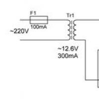 Smooth capacity charging: what to choose?
 Small Faculty of Mathematics
 “Why do you dream about a round dance in a dream?
 Why do you dream about the church inside: interpretation of the meaning of the dream according to various dream books for men and women
 Dream interpretation of persimmon, why do you dream of persimmon in a dream to see Persimmon in a dream why
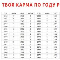 Enchanted soul Meaning of karmic numbers