Reference frequency. Lecture notes: Metrological characteristics of electronic oscilloscopes. Additional options include
1. Bandwidth or transient response parameters. Passband is the frequency range in which the frequency response has a rolloff of no more than 3 dB relative to the value at the reference frequency. The reference frequency is the frequency at which the frequency response does not roll off. The value of the frequency response decline in dB is found from the relationship:
Where l f op- image value at the reference frequency,
l f meas.- image size at the frequency for which the frequency response decay is measured.
2. Uneven frequency response.
3. Nonlinearity of the amplitude characteristic of the EO amplifier: β a =(l-1)*100%, Where l– the size of the signal image most different from one division of the screen scale anywhere in the working area of the screen. It is measured by applying a pulse or sinusoidal signal with an amplitude to the oscilloscope input with an amplitude that ensures that a signal image the size of one scale division is obtained in the center of the CRT screen. Then the size of the signal image is measured in various places on the working part of the screen, moving it along the vertical axis using an external voltage source.
4. Quality of signal reproduction in pulsed EO. This quality is characterized by the parameters of the transient response (TC):

4.1. Rise time of the transient response (TC) - τ n measured under the following conditions: pulses are supplied to the EO input with a rise time of no more than 0.3 of the rise time of the PH specified in the passport, standards or technical documentation for a specific type of EO. The pulse duration must be at least 10 times longer than the PH rise time. Surges on a pulse should not exceed 10% of the pulse image rise time, during which the beam deviates from a level of 0.1 to a level of 0.9 of the pulse amplitude;
4.2. Overshoot value: δ u = (l B / lu)*100%, Where l B– amplitude of the ejection image, l u- amplitude of the pulse image. Definition δu produced on pulses of positive and negative polarity.
4.3. Decay of the top of the pulse image: l JV(the value of the pulse decay value) is measured by applying a pulse with a duration of more than 25 to the input of the vertical deflection channel τ n with an amplitude that provides the maximum size of the pulse image in the working part of the CRT screen. The decay value of the pulse apex is measured from its image at a point distant from the beginning of the pulse by a time equal to its duration. The value is normalized relative to the decay of the top of the pulse, which is determined by the formula: Q=l SP /l u
4.4. Unevenness of the top of the pulse image (reflection, synchronicity of pickup). Reflection value γ determined from the formula γ=(S 1 -S) / S, Where S 1– amplitude of surge or decline, S– beam line thickness specified in the standards or in the description for this EO. Synchronous pickups v determined by measuring the amplitudes superimposed on the image of oscillations caused by internal interference, synchronously starting the scan: v = (v 1 -S) / S, Where v 1– deflection of the CRT beam due to the imposition of oscillations caused by internal interference on the image. Knowing the parameters of the PH, you can determine the parameters of the frequency response: f B = 350/τ n (MHz), f n = Q / (2π τ u)(Hz).
5. Sensitivity (normal value of deviation coefficient): ε=l/U in...K d =1/ε=U in /l...δ K =(K d /K d0)*100%, Where ε - sensitivity, l– value of the pulse amplitude image, U in– input signal amplitude value, K d– signal deviation coefficient according to the op-amp, δ K– deviation coefficient error, K d0– nominal value K d specified in the technical documentation.
6. The parameters of the EO input with a bandwidth of up to 30 MHz are determined by direct measurement of R and C with appropriate instruments. For more broadband EOs in those. The description provides a method for determining these parameters.
7. Errors of the amplitude calibrator and time interval calibrator and their measurement. The measurement error of these parameters is determined by comparing the readings of the tested EO and a reference measuring device with a measurement error of the corresponding value that is 3 times smaller than that of the EO being verified.
8. Scan duration - the time of the forward sweep during which the beam runs through the entire working part of the screen in the horizontal direction. In modern EOs, the duration of the forward sweep stroke is T P specified as a sweep factor K r = T P /l T, δ r = (K r /K r nom -1)*100%, Where l T– length of the horizontal axis segment corresponding to the duration T P, δ р– sweep factor error, K r nom– nominal value of the sweep factor.
9. Scan nonlinearity: β р =(l-1)*100%, Where l– the duration of the time interval that is most different from 1 cm or one scale division anywhere in the working part of the scan within the working part of the screen.
Attention! Each electronic lecture notes is the intellectual property of its author and is published on the website for informational purposes only.
3.1 Purpose and use of the control panel frequency converter
On the control panel frequency converter There are 2 indication displays (4 digits, 7 segments), control buttons, an analog potentiometer, operation indicators and block indicators. Using the buttons, you can set functional parameters, issue control commands and control the work frequency converter.
Control panel display
When setting (viewing) the functional parameters of the converter, the codes of the corresponding parameters are displayed on the upper display of the control panel, and their values are displayed on the lower display.
In the operating mode of the converter, the current values of the quantities are displayed on both screens, which are selected using functional parameters F 001 and F 002, when an error occurs - status error code frequency converter.
Function buttons
|
Button |
Purpose |
|
Potentiometer |
Increase/decrease reference frequency value, PID control settings |
|
MENU |
Enter the menu to set/view the values of functional parameters. Function parameter values start flashing when they can be changed |
|
ENTER/VD |
In the mode of setting the values of functional parameters: writing (confirming) the selected parameter value to the internal memory frequency converter. When the operation is completed successfully, the recorded value stops flashing. In normal mode: Changes the top display display. |
|
CANCEL / ND |
In the setting mode: function parameter values: cancel the operation of changing the value of the functional parameter and enter the viewing mode of the functional parameters from the setting mode. Exit menu. In normal mode: Changes the lower display indication. |
|
In the mode of setting the values of functional parameters: go to the previous parameter or increase the value of the parameter; With the motor running and digital input active: Increase the frequency reference or reference for PID control (potentiometer function). In error display mode: advance to next error code. |
|
|
In the mode of setting the values of functional parameters: move to the next parameter or decrease the value of the parameter; With the motor running and digital input active: Reduce the reference frequency or reference for PID control (potentiometer function). In error display mode: go to the previous error code. |
|
|
START |
When controlled from the control panel: “forward rotation” command |
|
REVERSE / STEP |
When controlled from the control panel: REVERSE – “reverse rotation” command, STEP – “step mode” command (selected using the functional parameter F 014) |
|
STOP/RESET |
With the engine running: the speed gradually decreases, a frequency converter stops working. |
Indicators
|
Indicator group |
Name indicator |
Indicator status |
Explanations |
|
Block indicators |
Hz |
flashing |
Indication on the display of the value of the set task for the reference frequency |
|
Hz |
lit |
Indication on the display of the output frequency value |
|
|
lit |
Indication on the display of the actual output current value |
||
|
lit |
Indication on the display of the percentage of output current |
||
|
flashing |
Indication on the display of the value of the remaining time, percentage for each step of the operating program |
||
|
lit |
Indication on the display of the input voltage value |
||
|
flashing |
Indication on the display of the output voltage value |
||
|
rpm |
lit |
Indication on the display of the engine speed value |
|
|
MPa |
flashing |
Indication on the display of the value of the set pressure target |
|
|
MPa |
lit |
Indication of the feedback pressure value on the display |
|
|
None of the indicators are lit |
Indication on the display of the total operating time |
||
|
Operation indicators |
M/D |
lit |
Local control mode frequency converter(using the remote control) |
|
NAPR |
lit |
Installation frequency converter coincides with the direction of rotation of the engine |
|
|
NAPR |
flashing |
Installation frequency converter does not match the direction of rotation of the engine |
|
|
STRAIGHT |
lit |
||
|
STRAIGHT |
flashing |
Engine rotates forward, no load |
|
|
ROAR |
lit |
Reverse rotation of the engine, |
|
|
ROAR |
flashing |
Reverse rotation of the engine, no load |
|
Viewing and changing function parameter values frequency converter
IN frequency converters STA series C 5. CP/STA- C 3. CS there are more than two hundred functional parameters stored in the internal memory, the values of which can be viewed and changed, thereby forming various operating modes and a general operating algorithm frequency converter. The values of most parameters can be changed during operation frequency converter(for more details, see the table of functional parameters), and they are automatically saved when it is turned off.
For example, you need to change the carrier frequency of the inverter from 3 kHz (factory setting) to 6 kHz. Then you need to do the following:
|
Functional button |
Condition Status frequency converter |
Control panel display data frequency converter(top and bottom respectively) |
Explanations |
|
The converter is in operating mode or stopped (power is supplied to the converter) |
The upper and lower displays indicate the values of the quantities specified by the functional parameters F 001 and F 002 respectively |
||
|
MENU |
Enter the menu of the functional parameters of the converter. View Mode |
The upper display shows the code of the functional parameter that was last set during operation of the converter, the lower display shows its current value |
|
|
Selecting a functional parameter whose value you want to view or change |
The upper display shows the code of the user-selected functional parameter, the lower display shows its current value |
||
|
MENU |
Entering the mode of changing the value of a functional parameter |
The upper display shows the code of the user-changeable functional parameter, the lower display shows its current value flashing |
|
|
Selecting the value of a functional parameter |
The upper display shows the code of the user-changeable functional parameter, the lower display flashes the value selected by the user |
||
|
ENTER /VD |
Confirmation of the set value of the functional parameter |
The upper display shows the code of the user-changeable functional parameter, the lower display shows the user-selected value stops flashing |
|
|
CANCEL / ND |
Exiting the Functional Parameters Menu frequency converter |
Return to original state frequency converter, but with a modified carrier frequency (6 kHz) |
3.2 Test run frequency converter
Control mode selection frequency converter
IN frequency converters STA series C 5. CP/STA- C 3. CS There are two main control modes frequency converter in operating mode: local (from the converter control panel) and remote (from the converter control terminals or via the interface R.S. -485). To determine the control mode of the frequency converter, a functional parameter is used F003.
Before the test run
Before the test run, check the correct connection of the power circuits, the tightness of the bolts, the routing of the wires, the integrity of the power cables, and the load.
During the test run
During the test run, make sure that the engine accelerates and stops smoothly, rotates in the specified direction, there are no unusual vibrations, unusual sounds, and the displays display accurate values.
Checking the direction of rotation of the motor
When power is applied to a frequency converter, the upper display of the control panel displays the inscription “C T.A. ", then both displays show the value "0.00" (if this value is greater than 0.00, turn the potentiometer to the leftmost position). The block indicators “Hz” and the operation indicator “M/D” begin to light up. This means that the reference frequency is indicated on the upper display, and the output frequency on the lower display.
Press and hold the REVERSE / STEP button, it starts frequency converter, the operation indicators “VOLTAGE” and “DIRECT” begin to light up. The upper display of the control panel displays the value of the reference frequency for the step mode - 5.00 Hz, the lower screen displays the output frequency (from 0.00 to 5.00 Hz), which, in accordance with the acceleration time in the step mode (functional parameter F032), increases to 5 Hz ( to the reference frequency). Release the REVERSE/STEP button. The display on the lower display of the control panel decreases to zero (the engine stops). The display value returns to its original value.
If the motor rotates in a direction different from the required one, then it is necessary to change the value of functional parameter F046. Change the order of connecting phases in a connection frequency converter and there is no need for an engine.
Using the control panel potentiometer during start-up
Apply power to a frequency converter, both control panel displays show the value “0.00”, if this value is greater than 0.00, be sure to turn the inverter control panel potentiometer to the extreme left position. The block indicators “Hz” and the operation indicator “M/D” begin to light up.
Press the START button, the “VOLTAGE” indicator lights up and the “DIRECT” indicator starts flashing. The inverter operates by producing an output frequency that is less than the minimum starting frequency. Turn the potentiometer clockwise to set the reference frequency of the converter. Now the upper display of the control panel displays the set reference frequency, and the lower display shows the output frequency, increasing from 0.00 Hz to the reference frequency value in accordance with the acceleration time of the converter (functional parameter F 019).
Also check other operating parameters of the inverter such as voltage, current using the ENTER/VD and CANCEL/ND function keys.
When the STOP/RESET function button is pressed, the inverter stops operating, reducing the output frequency from the reference (output if the reference has not yet been reached) to zero.
Setting/changing the converter reference frequency
 Let's say it is necessary in local control mode frequency converter with constant acceleration and deceleration times, start the engine at a reference frequency of the supply voltage of 20 Hz in the forward direction, then accelerate it in the same direction to the rated speed at a reference frequency of the supply voltage of 50 Hz (the reference frequency setting mode is digital from the converter control panel), then carry out a reverse at a reference frequency of the supply voltage of 50 Hz and stop.
|
|
Action |
Functional purpose of the action |
Display indications |
Explanations |
|
1. Power supply to the converter |
The displays show the default settings for the inverter: reference frequency - upper display, output frequency - lower display. Indicators "M/D " and "Hz" on the lower display light up, and the "Hz" indicator on the upper display blinks. |
||
|
2. Selecting the mode for setting the reference frequency of the converter: MENU MENU ENTER/VD |
Entering the functional parameters menu frequency converter. Parameter viewing mode. Search for the code of the parameter of interest ( F 004). Entering parameter change mode. Changing the parameter value from 1 to 0. Confirmation of the changed value. |
The upper display shows the code of the functional parameter that was last set during operation of the converter, and the lower display shows its current value. The upper display shows the code of the functional parameter, the lower display shows its current value. The parameter value starts flashing. The parameter value has been changed but continues to flash. The parameter value is set and stops flashing. |
|
|
3. Changing the inverter reference frequency to 20 Hz: MENU MENU ENTER/VD |
Changing the value of a function parameter F 013 from 50.00 to 20.00. |
………… |
Same as in point 2. |
|
4. Exit the converter functional parameters menu: CANCEL / ND The indication on the displays has the following meanings: set reference frequency - upper display, output frequency - lower display. |
|||
|
5. Starting the motor in the forward direction with a reference frequency of 20 Hz: START |
The indication on the displays has the following meanings: the upper display is the reference frequency, the lower display is the output frequency, the value of which increases from 0.00 to 20.00 in accordance with the set acceleration time (functional parameter F 019). The “DIRECT” indicator lights up. |
||
|
6. Increasing the reference frequency to 50 Hz: |
Hold the change button until the required value is obtained. |
The reference frequency (upper display) increases to 50.00, the output frequency (lower display) also increases to 50.00, but not instantly, but according to the set acceleration time. |
|
|
7. Reverse rotation of the motor with a reference frequency of 50 Hz: MENU MENU ENTER/VD CANCEL / ND REVERSE / STEP |
Entering the functional parameters menu frequency converter, change the parameter value F 014 from 0 to 1 and exit the menu. The reference frequency (upper display) corresponds to 50.00, the output frequency (lower display) decreases to 0.00, and then increases to 50.00 according to the set deceleration time and acceleration time (function parameters F 020 and F 019 respectively). The “NAPR” indicator flashes when the speed decreases, and stops flashing when it increases. The “ROAR” indicator lights up. |
||
|
8. View the converter output current: ENTER/VD |
Press the button until the inverter output current appears. |
The indication on the displays has the following meanings: the upper display is the output current of the converter, the lower display is the output frequency. The “Hz” indicator on the top display goes off and the “A” indicator lights up. |
|
|
9. Stopping the engine: The inverter output current (upper display) is reduced to 0.0, and the output frequency (lower display) is also reduced to 0.00 according to the set deceleration time. |
Frequency synthesis - the formation of a discrete set of frequencies from one or more reference frequencies f on. The reference frequency is a highly stable frequency of a self-oscillator, usually quartz.
Frequency synthesizer (MF) is a device that implements the synthesis process. The synthesizer is used in radio receiving and radio transmitting devices of radio communication systems, radio navigation, radar and other purposes.
The main parameters of the synthesizer are: the frequency range of the output signal, the number N and the frequency grid step Df w, long-term and short-term frequency instability, the level of spurious components in the output signal and the transition time from one frequency to another. In modern synthesizers, the number of discrete frequencies generated by it can reach tens of thousands, and the grid step can vary from tens of hertz to tens and hundreds of kilohertz. Long-term frequency instability, determined by a quartz self-oscillator, is 10 –6, and in special cases - 10 –8 ... 10 –9. The frequency range of a synthesizer varies widely depending on the purpose of the equipment in which it is used.
Practical frequency synthesizer designs are very diverse. Despite this diversity, we can note the general principles underlying the construction of modern synthesizers:
All synthesizers are based on the use of one highly stable reference oscillation with a certain frequency f 0, the source of which is usually a reference crystal oscillator;
The synthesis of multiple frequencies is carried out by the extensive use of dividers, multipliers and frequency converters, ensuring the use of one reference oscillation to form a frequency grid;
Providing frequency synthesizers with a ten-day setting of the exciter frequency.
Based on the method of generating output oscillations, synthesizers are divided into two groups: those made using the direct (passive) synthesis method and those made using the indirect (active) synthesis method.
The first group includes synthesizers in which output oscillations are formed by dividing and multiplying the frequency of the reference oscillator, followed by adding and subtracting the frequencies obtained as a result of division and multiplication.
The second group includes synthesizers that generate output oscillations in a range self-oscillator of harmonic oscillations with parametric frequency stabilization, the instability of which is eliminated by an automatic frequency control (AFC) system based on reference (highly stable) frequencies.
Synthesizers of both groups can be made using analog or digital element base.
Synthesizers made using the direct synthesis method.

A highly stable quartz oscillator generates oscillations with a frequency f 0 , which are supplied to the frequency dividers and multipliers of the MF and HF frequencies.
Frequency dividers reduce the exhaust gas frequency f 0 by an integer number of times (d), and frequency multipliers increase it by an integer number of times (k). The frequencies obtained as a result of dividing and multiplying the frequency of the reference oscillator (f 0) are used to form reference frequencies in special devices called reference frequency sensors. The total number of reference frequency sensors in a midrange frequency synthesizer depends on the range of frequencies generated by the synthesizer and the interval between adjacent frequencies: the wider the midrange frequency range and the smaller the interval, the greater the number of frequency frequencies required. With a ten-day frequency setting, each DFC generates ten reference frequencies with a certain interval between adjacent frequencies. The total number of required sensors is determined by the number of digits (bits) in the record of the maximum frequency of the synthesizer.
The reference frequencies generated in the sensors are fed to the mixers. Bandpass switchable filters included at the output of the mixers highlight the total frequency in this example: at the output of the first f 1 + f 2 , at the output of the second f 1 + f 2 + f 3 , at the output of the third f 1 + f 2 + f 3 + f 4 .
The frequency at the exciter output with a ten-day setting is determined by the positions of the switches of each decade.
The relative frequency instability at the synthesizer output is equal to the instability of the exhaust gas. The disadvantage of this type of synthesizer is the presence of a large number of combination frequencies at its output, which is explained by the widespread use of mixers.
Frequency synthesizers built using the indirect synthesis method
In synthesizers made using the indirect synthesis method, the source of output oscillations is a range self-oscillator of harmonic oscillations, automatically adjusted to highly stable frequencies generated in the reference frequency block of the BOCH.
The essence of automatic frequency adjustment of the AFC is that the oscillator oscillations using highly stable frequencies are converted to a certain constant frequency f of the AFC, which is compared with the reference frequency value. If the compared frequencies do not match, a control voltage is generated, which is supplied to the controlled reactive element and changes the value of its reactivity (capacitance or inductance).
Controlled reactive elements are included in the circuit that determines the frequency of the AG. The AG frequency changes until f AFC approaches the reference frequency with a sufficiently small residual detuning.
Depending on the comparison device, all AFC systems can be divided into three types:
Frequency-controlled automatic control systems, in which frequency detectors of black holes are used as a comparison device;
Systems with phase-locked loop phase locking loop, using phase detectors PD as a comparing device;
Systems with pulse-phase automatic frequency control (IFAP), in which the comparing device is pulse-phase detectors IPD.
Synthesizers with phase-locked loop phase locking, unlike
synthesizers with CAP do not have residual detuning. In the PLL system, the comparing device is the PD phase detector. The control voltage at the PD output is proportional to the phase difference between the two oscillations applied to it, the frequencies of which are equal in steady state.


Two oscillations of close frequencies are supplied to the PD: one of which is a reference with frequency f 0 generated in the barrel, the second is a product of converting the oscillations of the oscillator in the mixer using a frequency grid f 01 with the barrel
f PR = f UG – f 01.
If f PR and f 0 are close in value, then the control voltage from the PD output compensates for the detuning of the control unit and f PR = f 0, and a stationary mode is established in the system. However, the PLL system operates in a very narrow frequency band, not exceeding a few kHz. To ensure the tuning of the ultrasonic waveform throughout its entire frequency range, an auto-search system is used in a synthesizer with a phase-locking loop, which, by changing the frequency of the ultrasonic waveform throughout the entire frequency range, ensures that it falls within the coverage band of the phase-locking loop system. The auto-search system is a sawtooth voltage self-oscillator, which starts when there is no control voltage at the output of the low-pass filter. As soon as the frequencies of the UG fall into the capture band of the PLL system, the search generator is turned off, the system enters the auto-tuning mode with dynamic equilibrium f PR = f 0 .
The use of logic elements in the midrange led to the emergence of new types of synthesizers, which are called digital. They have significant advantages over analogue ones. They are simpler, more reliable in operation, and have smaller dimensions and weight.
The use of logical integrated circuits in the digital frequency converter made it possible to almost completely eliminate the frequency conversion of the UG, replacing the converters with a frequency divider with a variable division coefficient DPKD.
Block diagram of a synthesizer with one phase-locked loop loop

In the DPKD diagram - a divider with a variable division coefficient - a K-bit programmable digital counter. The purpose of the other links of the circuit is clear from the inscriptions made on them. The control unit receives and stores programming data and generates a code signal, which sets the value of the division coefficient N depending on the command received by the synthesizer. As a result of the action of phase-locked frequency control, the equality of the frequencies of the signals arriving at the input of the pulse-phase discriminator is established: f 1 = f 2, which allows us to write the following relationship for the frequencies of the stabilized and reference self-oscillators, taking into account the values of the division coefficients:

According to the frequency grid step Df w =f fl /M. By changing the controlled value N, the required frequency value of the stabilized generator is set, which, with the help of a control element, can be tuned in the required frequency range.
Currently, when developing electronic equipment, great attention is paid to the stability of its characteristics. Mobile radio communications, including cellular communications, are no exception. The main condition for achieving stable characteristics of electronic equipment components is the stability of the frequency of the master oscillator.
Any electronic equipment, including receivers, transmitters, and microcontrollers, usually contains a large number of generators. Initially, efforts had to be made to ensure frequency stability of all generators. With the development of digital technology, people have learned to form an oscillation of any frequency from one original frequency. As a result, it became possible to allocate additional funds to increase the frequency stability of ONE oscillator and thereby obtain a whole range of frequencies with very high stability. This frequency generator is called reference generator
Initially, special design methods were used to obtain stable oscillations of LC generators:
- The change in inductance due to the expansion of the wire metal was compensated by choosing a core material, the effect of which was the opposite of that of the inductance conductors;
- the metal was burned into a ceramic core with a low temperature coefficient of expansion;
- capacitors with different temperature coefficients of capacitance (TKE) were included in the circuit.
In this way, it was possible to achieve a stability of the reference oscillator frequency of 10 -4 (at a frequency of 10 MHz the frequency drift was 1 kHz)
At the same time, work was carried out on the use of completely different methods for obtaining stable oscillations. String, tuning fork, and magnetostrictive generators were developed. Their stability reached very high values, but at the same time their dimensions, complexity and price prevented their wide distribution. A revolutionary breakthrough was the development of generators using. One of the most common quartz oscillator circuits, made on a bipolar transistor, is shown in Figure 1.
Figure 1. Circuit of a crystal oscillator based on a bipolar transistor
In this reference oscillator circuit, amplitude balance is provided by transistor VT1 and phase balance is provided by circuit Z1, C1, C2. The generator is assembled according to the standard. The difference is that instead of an inductor, a quartz resonator Z1 is used. It should be noted that in this scheme it is not necessary to use . Often it turns out to be quite enough. A similar diagram is shown in Figure 2.

Figure 2. Schematic of a crystal oscillator with collector mode stabilization
The quartz oscillator circuits shown in Figures 1 and 2 make it possible to obtain a stability of the reference oscillation frequency of the order of 10 -5. The short-term stability of the oscillations of the reference oscillator has the greatest influence on the load. If there are extraneous oscillations at the output of the reference oscillator, its oscillations can be captured. As a result, the crystal oscillator will produce oscillations at the interference frequency. To prevent this phenomenon from manifesting itself in the reference oscillator, an amplifier is usually installed at its output, the main purpose of which is not to allow external oscillations to pass into the quartz oscillator. A similar diagram is shown in Figure 3.

Figure 3. Circuit of a quartz oscillator with decoupling of frequency-setting circuits from the circuit output
An equally important parameter that largely determines the phase noise of the oscillator (for digital circuits - jitter of the synchronization signal) is the supply voltage, therefore reference crystal oscillators are usually powered from a highly stable, low-noise voltage source and the power is filtered by RC or LC circuits.
The greatest contribution to the frequency instability of the quartz oscillator is made by the temperature dependence of the resonant frequency of the quartz resonator. In the manufacture of crystal reference oscillator resonators, AT-cuts are usually used, which provide the best frequency stability depending on temperature. It is 1*10 -5 (10 millionths or 10 ppm). An example of the dependence of the frequency of quartz resonators with AT-cut on temperature at different cut angles (cut angle step 10") is shown in Figure 4.

Figure 4. Dependence of the frequency of quartz resonators with AT-cut on temperature
A frequency instability of 1*10 -5 is sufficient for most radio-electronic devices, so quartz oscillators are used very widely without special measures to increase frequency stability. Crystal-stabilized reference oscillators without additional frequency stabilization measures are called XO.
As can be seen from Figure 4, the dependence of the tuning frequency of an AT-cut quartz resonator on temperature is well known. Moreover, this dependence can be removed experimentally for each specific instance of a quartz resonator. Therefore, if you constantly measure the temperature of the quartz crystal (or the temperature inside the quartz reference oscillator), then the oscillation frequency of the reference oscillator can be shifted to the nominal value by increasing or decreasing the additional capacitance connected to the quartz resonator.
Depending on the frequency control circuit, such reference oscillators are called TCXO (temperature-compensated crystal oscillators) or MCXO (microcontroller-controlled crystal oscillators). The frequency stability of such quartz reference oscillators can reach 0.5*10 -6 (0.5 millionths or 0.5 ppm)
In some cases, reference oscillators provide the ability to adjust the nominal generation frequency within small limits. Frequency adjustment is carried out by voltage applied to a varicap connected to a quartz resonator. The frequency adjustment range of the generator does not exceed a fraction of a percent. Such a generator is called VCXO. Part of the reference oscillator circuit (without thermal compensation circuit) is shown in Figure 5.

Figure 5. Voltage controlled crystal oscillator (VCXO)
Currently, many companies produce reference oscillators with frequency stability up to 0.5 * 10 -6 in small-sized housings. An example of a drawing of such a reference generator is shown in Figure 6.

Figure 6. External view of a reference crystal oscillator with temperature compensation
Literature:
Along with the article "Reference oscillators" read:
http://site/WLL/KvGen.php
http://site/WLL/synt.php
According to the latest statistics, approximately 70% of all electricity generated in the world is consumed by electric drives. And every year this percentage is growing.
With a correctly selected method of controlling an electric motor, it is possible to obtain maximum efficiency, maximum torque on the shaft of the electric machine, and at the same time the overall performance of the mechanism will increase. Efficiently operating electric motors consume a minimum of electricity and provide maximum efficiency.
For electric motors powered by an inverter, the efficiency will largely depend on the chosen method of controlling the electrical machine. Only by understanding the merits of each method can engineers and drive system designers get the maximum performance from each control method.
Content:
Control methods
Many people working in the field of automation, but not closely involved in the development and implementation of electric drive systems, believe that electric motor control consists of a sequence of commands entered using an interface from a control panel or PC. Yes, from the point of view of the general hierarchy of control of an automated system, this is correct, but there are also ways to control the electric motor itself. It is these methods that will have the maximum impact on the performance of the entire system.
For asynchronous motors connected to a frequency converter, there are four main control methods:
- U/f – volts per hertz;
- U/f with encoder;
- Open-loop vector control;
- Closed loop vector control;
All four methods use PWM pulse width modulation, which changes the width of a fixed signal by varying the width of the pulses to create an analog signal.
Pulse width modulation is applied to the frequency converter by using a fixed DC bus voltage. by quickly opening and closing (more correctly, switching) they generate output pulses. By varying the width of these pulses at the output, a “sinusoid” of the desired frequency is obtained. Even if the shape of the output voltage of the transistors is pulsed, the current is still obtained in the form of a sinusoid, since the electric motor has an inductance that affects the shape of the current. All control methods are based on PWM modulation. The difference between control methods lies only in the method of calculating the voltage supplied to the electric motor.
In this case, the carrier frequency (shown in red) represents the maximum switching frequency of the transistors. The carrier frequency for inverters is usually in the range of 2 kHz - 15 kHz. The frequency reference (shown in blue) is the output frequency command signal. For inverters used in conventional electric drive systems, as a rule, it ranges from 0 Hz to 60 Hz. When signals of two frequencies are superimposed on each other, a signal will be issued to open the transistor (indicated in black), which supplies power voltage to the electric motor.
U/F control method
Volt-per-Hz control, most commonly referred to as U/F, is perhaps the simplest control method. It is often used in simple electric drive systems due to its simplicity and the minimum number of parameters required for operation. This control method does not require the mandatory installation of an encoder and mandatory settings for a variable-frequency electric drive (but is recommended). This leads to lower costs for auxiliary equipment (sensors, feedback wires, relays, etc.). U/F control is quite often used in high-frequency equipment, for example, it is often used in CNC machines to drive spindle rotation.

The constant torque model has constant torque over the entire speed range with the same U/F ratio. The variable torque ratio model has a lower supply voltage at low speeds. This is necessary to prevent saturation of the electrical machine.
U/F is the only way to regulate the speed of an asynchronous electric motor, which allows the control of several electric drives from one frequency converter. Accordingly, all machines start and stop simultaneously and operate at the same frequency.
But this control method has several limitations. For example, when using the U/F control method without an encoder, there is absolutely no certainty that the shaft of an asynchronous machine rotates. In addition, the starting torque of an electric machine at a frequency of 3 Hz is limited to 150%. Yes, the limited torque is more than enough to accommodate most existing equipment. For example, almost all fans and pumps use the U/F control method.
This method is relatively simple due to its looser specification. Speed regulation is typically in the range of 2% - 3% of the maximum output frequency. The speed response is calculated for frequencies above 3 Hz. The response speed of the frequency converter is determined by the speed of its response to changes in the reference frequency. The higher the response speed, the faster the electric drive will respond to changes in the speed setting.
The speed control range when using the U/F method is 1:40. By multiplying this ratio by the maximum operating frequency of the electric drive, we obtain the value of the minimum frequency at which the electric machine can operate. For example, if the maximum frequency value is 60 Hz and the range is 1:40, then the minimum frequency value will be 1.5 Hz.
The U/F pattern determines the relationship between frequency and voltage during operation of a variable frequency drive. According to it, the rotation speed setting curve (motor frequency) will determine, in addition to the frequency value, also the voltage value supplied to the terminals of the electric machine.
Operators and technicians can select the desired U/F control pattern with one parameter in a modern frequency converter. Pre-installed templates are already optimized for specific applications. There are also opportunities to create your own templates that will be optimized for a specific variable frequency drive or electric motor system.
Devices such as fans or pumps have a load torque that depends on their rotation speed. The variable torque (picture above) of the U/F pattern prevents control errors and improves efficiency. This control model reduces magnetizing currents at low frequencies by reducing the voltage on the electrical machine.
Constant torque mechanisms such as conveyors, extruders and other equipment use a constant torque control method. With constant load, full magnetizing current is required at all speeds. Accordingly, the characteristic has a straight slope throughout the entire speed range.

U/F control method with encoder
If it is necessary to increase the accuracy of rotation speed control, an encoder is added to the control system. The introduction of speed feedback using an encoder allows you to increase the control accuracy to 0.03%. The output voltage will still be determined by the specified U/F pattern.
This control method is not widely used, since the advantages it provides compared to standard U/F functions are minimal. Starting torque, response speed and speed control range are all identical to standard U/F. In addition, when operating frequencies increase, problems with the operation of the encoder may arise, since it has a limited number of revolutions.
Open-loop vector control
Open-loop vector control (VC) is used for broader and more dynamic speed control of an electrical machine. When starting from a frequency converter, electric motors can develop a starting torque of 200% of the rated torque at a frequency of only 0.3 Hz. This significantly expands the list of mechanisms where an asynchronous electric drive with vector control can be used. This method also allows you to control the machine's torque in all four quadrants.

The torque is limited by the motor. This is necessary to prevent damage to equipment, machinery or products. The value of torques is divided into four different quadrants, depending on the direction of rotation of the electric machine (forward or reverse) and depending on whether the electric motor implements . Limits can be set for each quadrant individually, or the user can set the overall torque in the frequency converter.
The motor mode of an asynchronous machine will be provided that the magnetic field of the rotor lags behind the magnetic field of the stator. If the rotor magnetic field begins to outstrip the stator magnetic field, then the machine will enter regenerative braking mode with energy release; in other words, the asynchronous motor will switch to generator mode.
For example, a bottle capping machine may use torque limiting in quadrant 1 (forward direction with positive torque) to prevent overtightening of a bottle cap. The mechanism moves forward and uses the positive torque to tighten the bottle cap. But a device such as an elevator with a counterweight heavier than the empty car will use quadrant 2 (reverse rotation and positive torque). If the cabin rises to the top floor, then the torque will be opposite to the speed. This is necessary to limit the lifting speed and prevent the counterweight from free falling, since it is heavier than the cabin.
Current feedback in these frequency converters allows you to set limits on the torque and current of the electric motor, since as the current increases, the torque also increases. The output voltage of the inverter may increase if the mechanism requires more torque, or decrease if its maximum permissible value is reached. This makes the vector control principle of an asynchronous machine more flexible and dynamic compared to the U/F principle.
Also, frequency converters with vector control and open loop have a faster speed response of 10 Hz, which makes it possible to use it in mechanisms with shock loads. For example, in rock crushers, the load is constantly changing and depends on the volume and dimensions of the rock being processed.
Unlike the U/F control pattern, vector control uses a vector algorithm to determine the maximum effective operating voltage of the electric motor.

Vector control of the VU solves this problem due to the presence of feedback on the motor current. As a rule, current feedback is generated by the internal current transformers of the frequency converter itself. Using the obtained current value, the frequency converter calculates the torque and flux of the electrical machine. The basic motor current vector is mathematically split into a vector of magnetizing current (I d) and torque (I q).
Using the data and parameters of the electrical machine, the inverter calculates the vectors of the magnetizing current (I d) and torque (I q). To achieve maximum performance, the frequency converter must keep I d and I q separated by an angle of 90 0. This is significant because sin 90 0 = 1, and a value of 1 represents the maximum torque value.

In general, vector control of an induction motor provides tighter control. The speed regulation is approximately ±0.2% of the maximum frequency, and the regulation range reaches 1:200, which can maintain torque when running at low speeds.
Vector feedback control
Feedback vector control uses the same control algorithm as open-loop VAC. The main difference is the presence of an encoder, which allows the variable frequency drive to develop 200% starting torque at 0 rpm. This point is simply necessary to create an initial moment when moving off elevators, cranes and other lifting machines, in order to prevent subsidence of the load.
The presence of a speed feedback sensor allows you to increase the system response time to more than 50 Hz, as well as expand the speed control range to 1:1500. Also, the presence of feedback allows you to control not the speed of the electric machine, but the torque. In some mechanisms, it is the torque value that is of great importance. For example, winding machine, clogging mechanisms and others. In such devices it is necessary to regulate the torque of the machine.

 The story of the pilots who bombed Hiroshima and Nagasaki
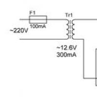 Smooth capacity charging: what to choose?
 Small Faculty of Mathematics
 “Why do you dream about a round dance in a dream?
 Why do you dream about the church inside: interpretation of the meaning of the dream according to various dream books for men and women
 Dream interpretation of persimmon, why do you dream of persimmon in a dream to see Persimmon in a dream why
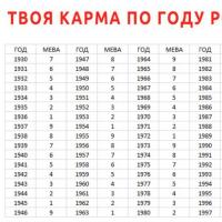 Enchanted soul Meaning of karmic numbers