Cos f smooth charging of capacitors. Smooth capacity charging: what to choose? Sergey Chemezov: Rostec is already one of the ten largest engineering corporations in the world
When designing amplifier power supplies Often problems arise that have nothing to do with the amplifier itself, or that are a consequence of the used element base. So in power supplies transistor amplifiers With high power, the problem often arises of implementing a smooth switching on of the power supply, that is, ensuring a slow charge of electrolytic capacitors in the smoothing filter, which can have a very significant capacity and, without taking appropriate measures, will simply damage the rectifier diodes at the moment of switching on.
In power supplies for tube amplifiers of any power, it is necessary to provide a feed delay high anode voltage before warming up the lamps, in order to avoid premature depletion of the cathode and, as a result, a significant reduction in the lamp life. Of course, when using a kenotron rectifier, this problem is solved by itself. But if you use a conventional bridge rectifier with an LC filter, you cannot do without an additional device.
Both of the above problems can be solved by a simple device that can be easily built into both a transistor and a tube amplifier.
Device diagram.
The schematic diagram of the soft start device is shown in the figure:

Click to enlarge
The alternating voltage on the secondary winding of transformer TP1 is rectified by the diode bridge Br1 and stabilized by the integrated stabilizer VR1. Resistor R1 ensures smooth charging of capacitor C3. When the voltage across it reaches a threshold value, transistor T1 will open, causing relay Rel1 to operate. Resistor R2 ensures the discharge of capacitor C3 when the device is turned off.
Inclusion options.
The Rel1 relay contact group is connected depending on the type of amplifier and the organization of the power supply.
For example, to ensure smooth charging of capacitors in the power supply transistor power amplifier, the presented device can be used to bypass the ballast resistor after charging the capacitors in order to eliminate power losses on it. A possible connection option is shown in the diagram:

The values of the fuse and ballast resistor are not indicated, since they are selected based on the power of the amplifier and the capacitance of the smoothing filter capacitors.
In a tube amplifier, the presented device will help organize a feed delay high anode voltage before the lamps warm up, which can significantly extend their service life. A possible inclusion option is shown in the figure:

The delay circuit here is turned on simultaneously with the filament transformer. After the lamps have warmed up, relay Rel1 will turn on, as a result of which the mains voltage will be supplied to the anode transformer.
If your amplifier uses one transformer to power both the lamp filament circuits and the anode voltage, then the relay contact group should be moved to the secondary winding circuit anode voltage.
Elements of the switch-on delay circuit (soft start):
- Fuse: 220V 100mA,
- Transformer: any low-power with an output voltage of 12-14V,
- Diode bridge: any small-sized one with parameters 35V/1A and higher,
- Capacitors: C1 - 1000uF 35V, C2 - 100nF 63V, C3 - 100uF 25V,
- Resistors: R1 - 220 kOhm, R2 - 120 kOhm,
- Transistor: IRF510,
- Integral stabilizer: 7809, LM7809, L7809, MC7809 (7812),
- Relay: with an operating winding voltage of 9V (12V for 7812) and a contact group of the appropriate power.
Due to the low current consumption, the stabilizer chip and field-effect transistor can be mounted without radiators.
However, someone may have the idea to abandon the extra, albeit small-sized, transformer and power the delay circuit from the filament voltage. Considering that the standard value of the filament voltage is ~6.3V, you will have to replace the L7809 stabilizer with an L7805 and use a relay with a winding operating voltage of 5V. Such relays usually consume significant current, in which case the microcircuit and transistor will have to be equipped with small radiators.
When using a relay with a 12V winding (somehow more common), the integrated stabilizer chip should be replaced with a 7812 (L7812, LM7812, MC7812).
With the values of resistor R1 and capacitor C3 indicated in the diagram delay time inclusions are of the order 20 seconds. To increase the time interval, it is necessary to increase the capacitance of capacitor C3.
The article was prepared based on materials from the magazine "Audio Express"
Free translation by the Editor-in-Chief of RadioGazeta.
If you connect a resistor and a capacitor, you get perhaps one of the most useful and versatile circuits.
Today I decided to talk about the many ways to use it. But first, about each element separately:
The resistor's job is to limit the current. This is a static element whose resistance does not change; we are not talking about thermal errors now - they are not too large. The current through a resistor is determined by Ohm's law - I=U/R, where U is the voltage at the resistor terminals, R is its resistance.
The capacitor is a more interesting thing. It has an interesting property - when it is discharged, it behaves almost like a short circuit - the current flows through it without restrictions, rushing to infinity. And the voltage on it tends to zero. When it is charged, it becomes like a break and the current stops flowing through it, and the voltage across it becomes equal to the charging source. It turns out an interesting relationship - there is current, no voltage, there is voltage - no current.
To visualize this process, imagine a balloon... um... a balloon that is filled with water. The flow of water is a current. Water pressure on elastic walls is the equivalent of stress. Now look, when the ball is empty - water flows freely, there is a large current, but there is almost no pressure yet - the voltage is low. Then, when the ball is filled and begins to resist pressure, due to the elasticity of the walls, the flow rate will slow down, and then stop altogether - the forces are equal, the capacitor is charged. There is tension on the stretched walls, but no current!
Now, if you remove or reduce the external pressure, remove the power source, then the water will flow back under the influence of elasticity. Also, the current from the capacitor will flow back if the circuit is closed and the source voltage is lower than the voltage in the capacitor.
Capacitor capacity. What is this?
Theoretically, a charge of infinite size can be pumped into any ideal capacitor. It’s just that our ball will stretch more and the walls will create more pressure, infinitely more pressure.
What then about Farads, what is written on the side of the capacitor as an indicator of capacitance? And this is just the dependence of voltage on charge (q = CU). For a small capacitor, the voltage increase from charging will be higher.
Imagine two glasses with infinitely high walls. One is narrow, like a test tube, the other is wide, like a basin. The water level in them is tension. The bottom area is the container. Both can be filled with the same liter of water - equal charge. But in a test tube the level will jump by several meters, and in a basin it will splash at the very bottom. Also in capacitors with small and large capacitance.
You can fill it as much as you like, but the voltage will be different.
Plus, in real life, capacitors have a breakdown voltage, after which it ceases to be a capacitor, but turns into a usable conductor :)
How quickly does a capacitor charge?
Under ideal conditions, when we have an infinitely powerful voltage source with zero internal resistance, ideal superconducting wires and an absolutely flawless capacitor, this process will occur instantly, with time equal to 0, as well as the discharge.
But in reality, there is always resistance, explicit - like a banal resistor, or implicit, such as the resistance of wires or the internal resistance of a voltage source.
In this case, the charging rate of the capacitor will depend on the resistance in the circuit and the capacitance of the capacitor, and the charge itself will flow according to exponential law.
 |
And this law has a couple of characteristic quantities:
- T - time constant, this is the time at which the value reaches 63% of its maximum. 63% was not taken by chance; it is directly related to the formula VALUE T =max—1/e*max.
- 3T - and at three times the constant the value will reach 95% of its maximum.
Time constant for RC circuit T=R*C.
The lower the resistance and lower the capacitance, the faster the capacitor charges. If the resistance is zero, then the charging time is zero.
Let's calculate how long it will take for a 1uF capacitor to be charged to 95% through a 1kOhm resistor:
T= C*R = 10 -6 * 10 3 = 0.001c
3T = 0.003s After this time, the voltage on the capacitor will reach 95% of the source voltage.
The discharge will follow the same law, only upside down. Those. after T time, only 100% - 63% = 37% of the original voltage remains on the capacitor, and after 3T even less - a measly 5%.
Well, everything is clear with the supply and release of voltage. What if the voltage was applied, and then raised further in steps, and then discharged in steps as well? The situation here will practically not change - the voltage has risen, the capacitor has been charged to it according to the same law, with the same time constant - after a time of 3T its voltage will be 95% of the new maximum.
It dropped a little - it was recharged and after 3T the voltage on it will be 5% higher than the new minimum.
What am I telling you, it’s better to show it. Here in multisim I created a clever step signal generator and fed it to the integrating RC chain:
 |
See how it wobbles :) Please note that both charge and discharge, regardless of the height of the step, are always of the same duration!!!
To what value can a capacitor be charged?
In theory, ad infinitum, a sort of ball with endlessly stretching walls. In reality, the ball will burst sooner or later, and the capacitor will break through and short-circuit. That’s why all capacitors have an important parameter - ultimate voltage. On electrolytes it is often written on the side, but on ceramic ones it must be looked up in reference books. But there it is usually from 50 volts. In general, when choosing a condenser, you need to ensure that its maximum voltage is not lower than that in the circuit. I will add that when calculating a capacitor for alternating voltage, you should choose a maximum voltage 1.4 times higher. Because on alternating voltage the effective value is indicated, and the instantaneous value at its maximum exceeds it by 1.4 times.
What follows from the above? And the fact is that if a constant voltage is applied to the capacitor, it will simply charge and that’s it. This is where the fun ends.
What if you submit a variable? It is obvious that it will either charge or discharge, and current will flow back and forth in the circuit. Movement! There is current!
It turns out that, despite the physical break in the circuit between the plates, alternating current easily flows through the capacitor, but direct current flows weakly.
What does this give us? And the fact that a capacitor can serve as a kind of separator to separate alternating and direct current into the corresponding components.
Any time-varying signal can be represented as the sum of two components - variable and constant.
 |
For example, a classical sinusoid has only a variable part, and the constant is zero. With direct current it is the opposite. What if we have a shifted sinusoid? Or constant with interference?
The AC and DC components of the signal are easily separated!
A little higher, I showed you how a capacitor is charged and discharged when the voltage changes. So the variable component will pass through the conder with a bang, because only it forces the capacitor to actively change its charge. The constant will remain as it was and will be stuck on the capacitor.
But in order for the capacitor to effectively separate the variable component from the constant, the frequency of the variable component must be no lower than 1/T
Two types of RC chain activation are possible:
Integrating and differentiating. They are also a low-pass filter and a high-pass filter.
The low-pass filter passes the constant component without changes (since its frequency is zero, there is nowhere lower) and suppresses everything higher than 1/T. The direct component passes directly, and the alternating component is quenched to ground through a capacitor.
Such a filter is also called an integrating chain because the output signal is, as it were, integrated. Do you remember what an integral is? Area under the curve! This is where it comes out.
And it is called a differentiating circuit because at the output we get the differential of the input function, which is nothing more than the rate of change of this function.
 |
- In section 1, the capacitor is charged, which means current flows through it and there will be a voltage drop across the resistor.
- In section 2, there is a sharp increase in the charging speed, which means the current will sharply increase, followed by a voltage drop across the resistor.
- In section 3, the capacitor simply holds the existing potential. No current flows through it, which means the voltage across the resistor is also zero.
- Well, in the 4th section the capacitor began to discharge, because... the input signal has become lower than its voltage. The current has gone in the opposite direction and there is already a negative voltage drop across the resistor.
And if we apply a rectangular pulse to the input, with very steep edges, and make the capacitance of the capacitor smaller, we will see needles like these:
rectangle. Well, what? That's right - the derivative of a linear function is a constant, the slope of this function determines the sign of the constant.
In short, if you are currently taking a math course, then you can forget about the godless Mathcad, disgusting Maple, throw the matrix heresy of Matlab out of your head and, taking out a handful of analog loose stuff from your stash, solder yourself a truly TRUE analog computer :) The teacher will be shocked :)
True, integrators and differentiators are usually not made using resistors alone; operational amplifiers are used here. You can google for these things for now, interesting thing :)
And here I fed a regular rectangular signal to two high- and low-pass filters. And the outputs from them to the oscilloscope:
Here's a slightly larger section:
When starting, the condenser is discharged, the current through it is full, and the voltage on it is negligible - there is a reset signal at the RESET input. But soon the capacitor will charge and after time T its voltage will already be at the level of logical one and the reset signal will no longer be sent to RESET - the MK will start.
And for AT89C51 it is necessary to organize exactly the opposite of RESET - first submit a one, and then a zero. Here the situation is the opposite - while the condenser is not charged, then a large current flows through it, Uc - the voltage drop across it is tiny Uc = 0. This means that RESET is supplied with a voltage slightly less than the supply voltage Usupply-Uc=Upsupply.
But when the condenser is charged and the voltage on it reaches the supply voltage (Upit = Uc), then at the RESET pin there will already be Upit-Uc = 0
Analog measurements
But never mind the reset chains, where it’s more fun to use the RC circuit’s ability to measure analog values with microcontrollers that don’t have ADCs.
This uses the fact that the voltage on the capacitor grows strictly according to the same law - exponential. Depending on the conductor, resistor and supply voltage. This means that it can be used as a reference voltage with previously known parameters.
It works simply, we apply voltage from the capacitor to an analog comparator, and connect the measured voltage to the second input of the comparator. And when we want to measure the voltage, we simply first pull the pin down to discharge the capacitor. Then we return it to Hi-Z mode, reset it and start the timer. And then the condenser begins to charge through the resistor, and as soon as the comparator reports that the voltage from the RC has caught up with the measured one, we stop the timer.
 |
Knowing according to which law the reference voltage of the RC circuit increases over time, and also knowing how long the timer has been ticking, we can quite accurately find out what the measured voltage was equal to at the time the comparator was triggered. Moreover, it is not necessary to count exponents here. At the initial stage of charging the condenser, we can assume that the dependence there is linear. Or, if you want greater accuracy, approximate the exponent with piecewise linear functions, and in Russian, draw its approximate shape with several straight lines or create a table of the dependence of a value on time, in short, the methods are simple.
If you need to have an analog switch, but don’t have an ADC, then you don’t even need to use a comparator. Jiggle the leg on which the capacitor hangs and let it charge through a variable resistor.
By changing T, which, let me remind you, T = R * C and knowing that we have C = const, we can calculate the value of R. Moreover, again, it is not necessary to connect the mathematical apparatus here, in most cases it is enough to take measurements in some conditional parrots, like timer ticks. Or you can go the other way, not changing the resistor, but changing the capacitance, for example, by connecting the capacitance of your body to it... what will happen? That's right - touch buttons!
If something is not clear, then don’t worry, I’ll soon write an article about how to attach an analog piece of equipment to a microcontroller without using an ADC. I'll explain everything in detail there.
You've got some cool fireworks going on. As soon as a couple of LEDs break through, the voltage on LM317 will jump to the limit and there will be great bang.
1000 microfarads at 450v = 80 Joules. In case of problems, the capacitor dries up so much that it doesn’t seem enough. But there will be problems, since you put the capacitor with absolutely no reserve in an environment where even 1kV can be caught in a pulse at the input.
Advice - make a normal pulse driver. And not this circle of “skillful hands” without galvanic isolation and filters.
Even if we conditionally accept this circuit as correct, you need to place ceramic capacitors around the LM317 so that it does not ring.
And yes, current limiting by a transistor is done differently - in your circuit it will simply explode because initially a network will be attached to the E-K junction.
And your divider will apply 236 volts to the EB junction, which will also lead to an explosion of the transistor.
After several clarifications, it finally became clear what you want to achieve: a common power source for several circuits of LEDs connected in series. You considered the main problem to be the smooth charging unit of the filter capacitor. In my opinion, there are several much more critical places in such a scheme. But first, on the topic of the question.
1000 μF is a value suitable for a load current of 0.5...3 amperes, and not tens of milliamps (22...50 μF is sufficient there). The transistor can be installed if you need to make a smooth increase in brightness for 4...20 seconds - but you have several garlands! Do they really have to start in the entire apartment at the same time? And about the switches - instead of the standard ones that switch the ~220 volt circuit, do you want to switch the ~310 volt circuit by placing a switch between the capacitor and the garland? This solution looks at least somehow justified for a “smart home” (and even then not everything in it is clear), but in an ordinary apartment there is no point in doing this. In it, it is more correct to install for each garland its own separate power supply - and then it is much more profitable to use ordinary super-cheap (and much more reliable!) tapes with parallel 12 volt LEDs, and not with homemade series ones, in which the burnout of one diode completely deprives you of light.
Another purpose of the smooth charge unit is to protect rectifier diodes from repeated overload at the moment of switching on, when the capacitor is completely discharged. But this problem can be completely solved by a much simpler method - instead of T1 and R1, R3, you need to insert a thermistor with a resistance of several tens of ohms, which decreases when warmed up to 0.5...3 ohms, this is done in hundreds of millions of computer power supplies that work reliably for years at approximately the same load current as yours. You can get such a thermistor from any dead computer power supply.
And finally, about what is not in your question, but it catches your eye - about the current stabilizer on the LM317, which absorbs excess mains voltage. The fact is that such a stub is operational only in the range from 3 to 40 volts. The tolerance for mains voltage in a healthy city network is 10%, i.e. from 198 to 242 volts. This means that if you calculated the stub at the lower limit (and this is usually done), then at the upper limit the voltage at the stub will go beyond the permissible 40 volts. If you set it to the top of the range (i.e., 242), then at the lower limit the voltage on the stub will drop below 3 volts, and it will no longer stabilize the current. And I won’t say anything about what will happen to this scheme in rural areas, where fluctuations in network voltage are much wider. So such a circuit will work normally only with a stable network voltage - but with a stable network, a stabilizer is not needed; it can be perfectly replaced by a simple resistor.
Let's connect a circuit consisting of an uncharged capacitor with a capacitance C and a resistor with a resistance R to a power source with a constant voltage U (Fig. 16-4).
Since at the moment of switching on the capacitor is not yet charged, the voltage across it. Therefore, in the circuit at the initial moment of time, the voltage drop across the resistance R is equal to U and a current arises, the strength of which

Rice. 16-4. Charging the capacitor.
The passage of current i is accompanied by a gradual accumulation of charge Q on the capacitor, a voltage appears on it and the voltage drop across the resistance R decreases:
![]()
as follows from Kirchhoff's second law. Therefore, the current strength
decreases, the rate of charge accumulation Q also decreases, since the current in the circuit
Over time, the capacitor continues to charge, but the charge Q and the voltage on it grow more and more slowly (Fig. 16-5), and the current in the circuit gradually decreases in proportion to the voltage difference

Rice. 16-5. Graph of changes in current and voltage when charging a capacitor.
After a sufficiently large time interval (theoretically infinitely long), the voltage on the capacitor reaches a value equal to the voltage of the power source, and the current becomes equal to zero - the charging process of the capacitor ends.
The process of charging a capacitor is longer, the greater the resistance of the circuit R, which limits the current, and the greater the capacitance of the capacitor C, since with a large capacitance a larger charge must accumulate. The speed of the process is characterized by the time constant of the circuit
the more , the slower the process.
The time constant of the circuit has the dimension of time, since
After a time interval from the moment the circuit is turned on, equal to , the voltage on the capacitor reaches approximately 63% of the power source voltage, and after the interval, the charging process of the capacitor can be considered completed.
Voltage across the capacitor when charging
i.e., it is equal to the difference between the constant voltage of the power source and the free voltage, which decreases over time according to the law of an exponential function from the value U to zero (Fig. 16-5).
Capacitor charging current
![]()
The current from the initial value gradually decreases according to the law of the exponential function (Fig. 16-5).
b) Capacitor discharge
Let us now consider the process of discharging capacitor C, which was charged from the power source to voltage U through a resistor with resistance R (Fig. 16-6, Where the switch is moved from position 1 to position 2).

Rice. 16-6. Discharging a capacitor to a resistor.

Rice. 16-7. Graph of changes in current and voltage when discharging a capacitor.
At the initial moment, a current will arise in the circuit and the capacitor will begin to discharge, and the voltage across it will decrease. As the voltage decreases, the current in the circuit will also decrease (Fig. 16-7). After a time interval, the voltage on the capacitor and the circuit current will decrease to approximately 1% of the initial values and the process of discharging the capacitor can be considered completed.
Capacitor voltage during discharge
![]()
i.e., it decreases according to the law of the exponential function (Fig. 16-7).
Capacitor discharge current
![]()
that is, it, like the voltage, decreases according to the same law (Fig. 6-7).
All the energy stored when charging a capacitor in its electric field is released as heat in resistance R during discharge.
The electric field of a charged capacitor, disconnected from the power source, cannot remain unchanged for a long time, since the dielectric of the capacitor and the insulation between its terminals have some conductivity.
The discharge of a capacitor due to imperfection of the dielectric and insulation is called self-discharge. The time constant during self-discharge of a capacitor does not depend on the shape of the plates and the distance between them.
The processes of charging and discharging a capacitor are called transient processes.
Often in various power supplies the task arises of limiting the starting current surge when turned on. The reasons may be different - rapid wear of relay contacts or switches, reduced service life of filter capacitors, etc. I recently had a similar problem. I use a good server power supply in my computer, but due to the unsuccessful implementation of the standby section, it overheats severely when the main power is turned off. Because of this problem, I had to repair the standby board twice already and change some of the electrolytes located next to it. The solution was simple - turn off the power supply from the outlet. But it had a number of disadvantages - when turned on, there was a strong surge of current through the high-voltage capacitor, which could damage it, in addition, after 2 weeks the power plug of the unit began to burn out. It was decided to make an inrush current limiter. In parallel with this task, I had a similar task for powerful audio amplifiers. The problems in amplifiers are the same - burning of switch contacts, current surge through the bridge diodes and filter electrolytes. You can find quite a lot of surge current limiter circuits on the Internet. But for a specific task, they may have a number of disadvantages - the need to recalculate circuit elements for the required current; for powerful consumers - selection of power elements that provide the necessary parameters for the calculated allocated power. In addition, sometimes it is necessary to provide a minimum starting current for the connected device, which increases the complexity of such a circuit. To solve this problem, there is a simple and reliable solution - thermistors.
Fig.1 Thermistor
A thermistor is a semiconductor resistor whose resistance changes sharply when heated. For our purposes, we need thermistors with a negative temperature coefficient - NTC thermistors. When current flows through the NTC thermistor, it heats up and its resistance drops.

Fig.2 TKS thermistor
We are interested in the following thermistor parameters:
Resistance at 25˚C
Maximum steady current
Both parameters are in the documentation for specific thermistors. Using the first parameter, we can determine the minimum current that will pass through the load resistance when connecting it through a thermistor. The second parameter is determined by the maximum power dissipation of the thermistor and the load power must be such that the average current through the thermistor does not exceed this value. For reliable operation of the thermistor, you need to take the value of this current less than 20 percent of the parameter specified in the documentation. It would seem that it would be easier to select the right thermistor and assemble the device. But you need to consider some points:
- The thermistor takes a long time to cool down. If you turn off the device and immediately turn it on again, the thermistor will have low resistance and will not perform its protective function.
- You cannot connect thermistors in parallel to increase the current - due to the spread of parameters, the current through them will vary greatly. But it is quite possible to connect the required number of thermistors in series.
- During operation, the thermistor becomes very hot. The elements next to it also heat up.
- The maximum steady-state current through the thermistor should be limited by its maximum power. This option is listed in the documentation. But if the thermistor is used to limit short current surges (for example, when the power supply is initially turned on and the filter capacitor is charging), then the pulse current may be greater. Then the choice of thermistor is limited by its maximum pulse power.
The energy of a charged capacitor is determined by the formula:
E = (C*Vpeak²)/2
where E is the energy in joules, C is the capacitance of the filter capacitor, Vpeak is the maximum voltage to which the filter capacitor will be charged (for our networks you can take the value 250V*√2 = 353V).
If the documentation indicates the maximum pulse power, then based on this parameter you can select a thermistor. But, as a rule, this parameter is not specified. Then the maximum capacity that can be safely charged with a thermistor can be estimated from the already calculated tables for thermistors of standard series.
I took a table with the parameters of NTC thermistors from Joyin. The table shows:
Rnom- nominal resistance of the thermistor at a temperature of 25°C
Imax- maximum current through the thermistor (maximum steady-state current)
Smax- maximum capacity in the test circuit that is discharged onto the thermistor without damaging it (test voltage 350v)
You can see how the test is carried out on page seven.
A few words about the parameter Smax– the documentation shows that in the test circuit the capacitor is discharged through a thermistor and a limiting resistor, which releases additional energy. Therefore, the maximum safe capacity that a thermistor can charge without such resistance will be less. I searched for information in foreign thematic forums and looked at typical circuits with limiters in the form of thermistors, for which data is given. Based on this information, you can take the coefficient for Smax in a real scheme 0.65, by which to multiply the data from the table.
|
Name |
Rnom, |
Imax, |
Smax, |
|
|
ddiameter 8mm |
||||
|
diameter 10mm |
||||
|
diameter 13mm |
||||
|
diameter 15mm |
||||
|
diameter 20mm |
||||
Table of parameters of NTC thermistors from Joyin
By connecting several identical NTC thermistors in series, we reduce the requirements for the maximum pulse energy of each of them.
Let me give you an example. For example, we need to select a thermistor to turn on the computer power supply. The maximum power consumption of the computer is 700 watts. We want to limit the starting current to 2-2.5A. The power supply contains a 470 µF filter capacitor.
We calculate the effective current value:
I = 700W/220V = 3.18A
As I wrote above, for reliable operation of the thermistor, we will select the maximum steady-state current from the documentation that is 20% greater than this value.
Imax = 3.8A
We calculate the required thermistor resistance for a starting current of 2.5A
R = (220V*√2)/2.5A = 124 Ohm
From the table we find the required thermistors. 6 pieces of JNR15S200L thermistors connected in series suit our needs Imax, general resistance. The maximum capacity that they can charge will be 680 µF * 6 * 0.65 = 2652 µF, which is even more than we need. Naturally, with a decrease Vpeak, the requirements for the maximum pulse power of the thermistor are also reduced. Our dependence is on the square of the voltage.
And the last question about the choice of thermistors. What if we have selected the thermistors required for maximum pulse power, but they are not suitable for us? Imax(the constant load is too high for them), or do we not need a source of constant heating in the device itself? To do this, we will use a simple solution - we will add another switch to the circuit in parallel with the thermistor, which we will turn on after charging the capacitor. Which is what I did in my limiter. In my case, the parameters are as follows: the maximum power consumption of the computer is 400W, the starting current limitation is 3.5A, the filter capacitor is 470uF. I took 6 pieces of 15d11 (15 ohm) thermistors. The diagram is shown below.

Rice. 3 Limiter circuit
Explanations for the diagram. SA1 disconnects the phase wire. LED VD2 serves to indicate the operation of the limiter. Capacitor C1 smoothes out ripples and the LED does not flicker at the mains frequency. If you don’t need it, then remove C1, VD6, VD1 from the circuit and simply connect the LED and diode in parallel in the same way as the elements VD4, VD5. To indicate the charging process of the capacitor, LED VD4 is connected in parallel with the thermistors. In my case, when charging the capacitor of the computer power supply, the entire process takes less than a second. So, let's collect.

Fig.4 Assembly kit
I assembled the power indicator directly in the cover of the switch, throwing out a Chinese incandescent lamp, which would not have lasted long.


Rice. 5 Power indicator

Fig.6 Thermistor block


Rice. 7 Assembled limiter
This could have been completed if all the thermistors had not failed after a week of work. It looked like this.

Rice. 8 Failure of NTC thermistors
Despite the fact that the margin for the permissible capacitance value was very large - 330 µF * 6 * 0.65 = 1287 µF.
I bought the thermistors from a well-known company, with different values - all defective. Manufacturer unknown. Either the Chinese pour thermistors of smaller diameters into large cases, or the quality of the materials is very poor. As a result, I bought an even smaller diameter - SCK 152 8mm. The same China, but already branded. According to our table, the permissible capacitance is 100 µF * 6 * 0.65 = 390 µF, which is even slightly less than needed. However, everything works fine.
 The story of the pilots who bombed Hiroshima and Nagasaki
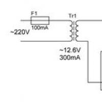 Smooth capacity charging: what to choose?
 Small Faculty of Mathematics
 “Why do you dream about a round dance in a dream?
 Why do you dream about the church inside: interpretation of the meaning of the dream according to various dream books for men and women
 Dream interpretation of persimmon, why do you dream of persimmon in a dream to see Persimmon in a dream why
 Enchanted soul Meaning of karmic numbers